GInOutHwExplorer
With Viper.NET the GInOutHwExplorer (or HwExplorer for short) is installed, which can be used to initialize and start the GInOut interface outside of Viper.NET.
The HwExplorer can be used to create and test GInOut configurations as well as to simulate remote stations (controls) via Python scripts. In Viper.NET the HwExplorer is included as User Tab.
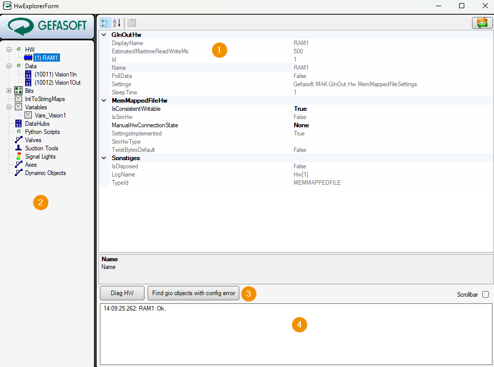
Surface HwExplorer
Settings for the selected object
All defined objects
Checking the connection
Status messages of the connected hardware
Creating new objects
Most objects like hardware or data are created via the context menu of the object tree on the left.
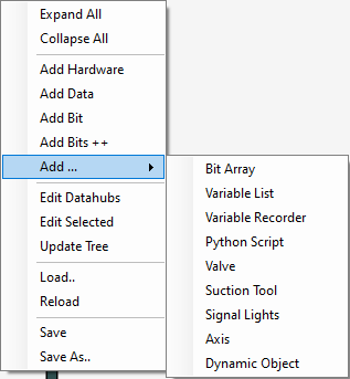
Exceptions are data blocks, which are created inside the hardware, and variables, which are defined in the variable list.
Hint
Objects can be created here, but can no longer be deleted. To delete, the configuration file must be edited directly.
Parameterization of objects
Objects can be parameterized when they are created, or by selecting or double-clicking them in the object tree. Some parameters, especially object IDs, can only be defined when creating the object. The parameters of the GInOut objects are described below.
Hardware and data blocks
The parameterization of hardware and data blocks depends on the respective hardware type and is explained in chapter Supported hardware.
Data
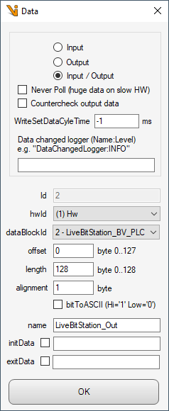
- Input, Output, Input/Output
Defines whether the data can only be read or written or used bidirectionally.
- Never poll (huge data on slow HW)
Normally the data area is polled cyclically. Large data areas on slow hardware can slow down the poll cycle and thus the response time of Viper.NET. Therefore such areas can be excluded from the poll cycle. The data will then be read only when needed.
- Countercheck output data
Only for input/output: Normally output data in Viper.NET is written only once. If unauthorized changes to the data are detected by the remote station (PLC), GInOut overwrites them with the actual output data and thus ensures the correct data state.
- WriteSetDataCycleTime
Similar to Countercheck output data, an interval for a cyclic update of the data can be specified here, which is also possible for pure output data.
- DataChangedLogger
For diagnostic purposes, all data changes can be logged. These are stored in the application log by default. A separate log file can also be defined via the log4net configuration file.
- Id
Unique ID of the data for further referencing, e.g. for the bits. Can only be set when creating the data object.
- Hardware and Datablock
Reference to the hardware and a data block within the hardware to which the data is mapped.
- Offset, Length
Offset and length of the data within the data block. Offset + Length must be less than the length of the data block.
- Alignment
Specifies the alignment of the data. In most cases this must be 1. Exception is for example the Modbus connection.
- BitToASCII
In special cases or for special hardware (Prodel) it can be specified here that bits are mapped as ASCII 0 or 1 instead of binary.
- Name
A descriptive name for the data.
- InitData
Sets the data at program start. If no binary is specified, the data is set to 0x00.
- ExitData
Sets the data at the end of the program. If no binary is specified, the data is set to 0x00.
Bits
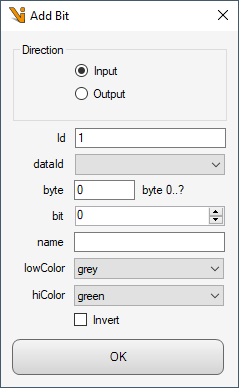
- Direction
Defines an input or output bit.
- Id
Unique ID of the data for further referencing. Can only be set when creating the data object.
- Data, byte and bit
Reference to the data, the byte offset and the bit index within the byte to which the bit is mapped.
- Name
Freely selectable designation for the bit.
- LowColor, HighColor
Defines the colors of the visualization for the HIGH or LOW state.
- Invert
If set, the bit is interpreted inverted.
Variables
Variable lists
Variables are always organized in variable lists. After creating the variable list via the context menu, the variables can be defined:
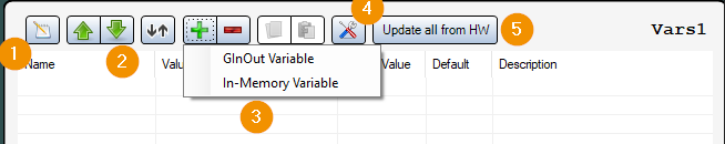
Change the value of the selected variable (alternatively: double-click on the variable in the list)
Sort list (up, down, automatically by dates and offset)
Create, delete, copy and paste variables
Rename List
Reads the values of all variables from the hardware
GInOut variables
In most cases GInOut variables are used whose value is read or written from GInOut data.
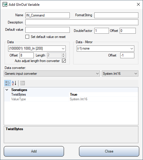
- Name
Speaking name of the variable. Must be unique within the variable list.
- FormatString
Can be used for the representation as text. Depending on the data type or converter, other values are permitted here. The format identifiers of .NET are supported.
- Description
Optional description
- Default value
Default value to which the variable is to be reset in certain cases. The value is entered as text. This text must be able to be converted into the data type of the variable or the converter. If empty, the default value of the data type is used (e.g. 0 for numeric types).
- Set default value on reset
If set, the variable will be reset to its default value when Viper.NET is reset.
- DoubleFactor
Can be used with numeric data types, e.g. to convert values transmitted by the PLC in micrometers directly into millimeters.
- Offset
If set, will be added to the numeric variable value after applying the DoubleFactor.
- Data
Selection of GInOut data in which the variable resides, and offset and length of the variable in the data.
- Auto adjust length from converter
If set, the parameter Data.Length is automatically set to the length of the data type in the converter.
- Data - Mirror
Optional mirroring of data into a second data area.
- Data converter:
The data converter translates the value of the variable into a byte array and vice versa. This byte array is then written to the data or was read from the data. The parameters differ depending on the type and are documented here.
In-memory variables
These variables are not mapped to data, but are held in memory.
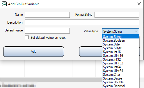
Most of the parameters correspond to those of the GInOut variable, except that no data range and converter specifications have to be made here. Instead, only the Value type must be specified.
Variable recorder
The value changes of variables can be recorded with a Variable Recorder for diagnostic purposes. Currently, only the graphical representation of numeric variable types is supported.
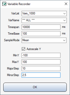
- VarList
Selection of the variable list.
- VarName
Selection of the variable to be recorded, or
*** ALL ***to record all variables of the list together.- Timespan
Time window for variable recording. Older values are discarded again.
- TimeBase
Refresh interval of the display
- SampleMode
Defines how multiple value changes should be aggregated within an update interval.
- Autoscale Y
If active, the Y-axis is automatically scaled based on the variable values
- MinY, MaxX, MajorStep, MinorStep
If Autoscale Y is deselected, the scaling and division of the Y-axis can be defined here.
Created variable recorders are listed in the object tree under the Variables node.
Python Scripts
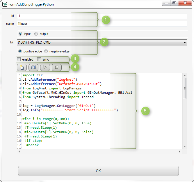
The name of the script can be freely chosen. Scripts can be referenced via the ID, e.g. in the UI Designer.
Selection of the trigger bit for the script.
“input/output”: preselection for the bit list
“bit”: selection of the bit
“positive/negative edge”: Specifies whether the script should be executed on positive or negative edge.
Enabled” sets whether the script should be executed when the state of the bit changes. “sync” specifies whether the script should be executed in a separate thread (not set).
Here
created a default script
translated the script (checked for syntax errors)
started the script
stopped the script (only possible if “sync” is not set)
Input of the Python script.
Axes
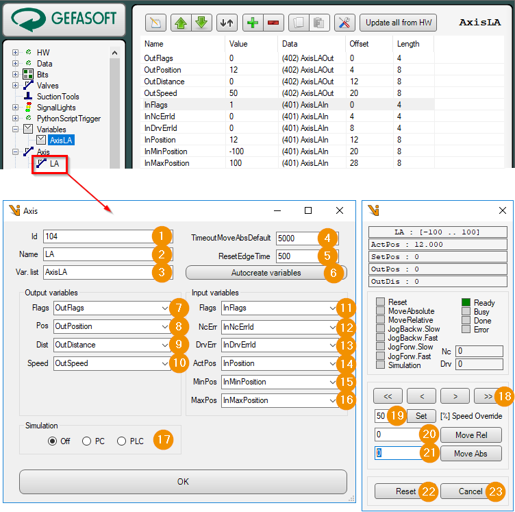
Id: Unique numeric ID of the axis. An axis is accessed via the GInOutManager with this ID.
Name: Display name for the axis.
Var. list: Name of the GInOut variable list. This contains all GInOut variables for data exchange with the PLC.
TimoutMoveAbsDefault: Maximum waiting time in [ms] for a movement of the axis.
ResetEdgeTime: Pulse duration in [ms] for the reset flag.
Autocreate variables: A new variable list for the data exchange to the PLC is created via a wizard.
Enter the name for the new list of variables.
Select input data range.
Select output data range.
Input-output variables are created automatically.
Output Flags: Signals from PC to PLC
Reset: Reset axis or acknowledge error.
MoveAbsolute: Move axis to position (variable Output Pos).
MoveRelative: Move axis relative to the current position (variable Output Dist).
JogBackw.Slow: Move axis slowly backwards as long as the flag is ON.
JogBackw.Fast: Move axis backward fast as long as flag is ON.
JogForw.Slow: Move axis slowly forward as long as flag is ON.
JogForw.Fast: Move axis forward fast as long as flag is ON.
Simulation: Activate simulation mode in the PLC.
Output Pos: Position register for absolute axis movements.
Output Dist: Position register for relative axis movements (distance).
Output Speed: Axis speed in [%] to the maximum speed (set in the PLC).
Input Flags: Signals from the PLC to the PC
Ready: Axis ready.
Busy: Run command is running.
Done: Travel command completed.
Error: An error is present.
Input NcErr: Error number of the controller.
Input DrvErr: Error number of the motor driver.
Input ActPos: Current axis position.
Input MinPos: Lower software limit for the position.
Input MaxPos: Upper software limit for the position.
Simulation: Simulation mode
Off: Simulation mode is off.
PC: Axis is simulated by the PC. The handshake to the PLC is simulated. For this Viper.NET should have been started with the command line parameter -simAllHw.
PLC: Axis is simulated by the PLC. The output flag Simulation is set before each move command.
Jog Buttons: Sets the corresponding flag for slow or fast forward or backward movement.
Speed Override: Set travel speed in [%].
Move Rel: Move axis relative to current position.
Move Abs: Move axis to position.
Reset: Reset axis or acknowledge error. The output flag Reset is pulsed.
Cancel: Cancel active move command.
Cylinders (Valves)
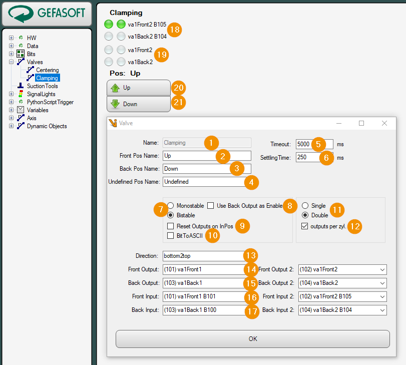
Name: Unique name of the cylinder. A cylinder is accessed via the GInOutManager with this name. The name can only be specified when creating a new cylinder.
Front Pos Name: Name for the working position of the cylinder.
Back Pos Name: Name for the home position of the cylinder.
Undefined Pos Name: Name for a position between the end positions.
Timeout: Maximum waiting time in [ms] for the movement of the cylinder from one end position to the other.
Settling Time: Settling time in [ms]. The WaitForIsSettled function ensures that the settling time is waited for since reaching the end position.
Valve Type
Monostable: The monostable cylinder is controlled via a single output.
Bistable: The bistable cylinder is controlled with two outputs. There is one output each for the home and working position. When the cylinder has reached the end position, the output can usually be reset.
Use Back Output as Enable: For monostable cylinders the output for the home position is used as enabled output.
Reset Outputs on InPos: Specifies whether the outputs should be reset when the end position is reached for bistable cylinders.
bitToASCII: Each bit is written as ASCII character into the data. Thereby one byte is needed for each bit (ON = ‘1’ = 0x31 ; OFF = ‘0’ = 0x30).
Single/Double: Cylinder type Single or double cylinder. The double cylinder has two slides. Each carriage has its own input signals for the end positions.
outputs per cyl.: Indicates whether a double cylinder has separate outputs for the second carriage to control the end position.
Direction: Direction of movement of the carriage from home position to working position. This setting changes the image and the position of keys 20 and 21.
left2right: Left -> Right
right2left: Right -> Left
bottom2top: Bottom -> Top
top2bottom: Top -> Bottom
Front Output: Output for controlling the working position.
Back Output: Output for controlling the home position for bistable cylinder, or optional activated output for monostable cylinder.
Front Input: Input for end positions signal working position.
Back Input: Input for end position signal home position.
Inputs: Visualization of the inputs.
Outputs: Visualization of the outputs.
GoTo Front: Move cylinder to working position.
GoTo Back: Move cylinder to home position.
Signal Lights
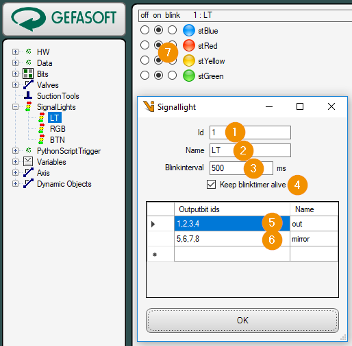
Id: Unique numeric ID of the signal light. A signal lamp is accessed via the GInOutManager with this ID.
Name: Display name for the signal light.
blinkinterval: On/off time in [ms] for the signal status blink.
Keep blink timer alive: If checked, the blink timer runs permanently and sets the signal status (on/off/blinking) cyclically.
Ouputbit ids out: List of output bits of the signal traffic light.
Ouputbit ids mirror: List of output bits to which the status of the signal light is to be mirrored, i.e. another signal light that is to display the identical status.
Signalstate: Current signal state: ‘Off’, ‘On’, ‘Flashing’.
Suction Tools
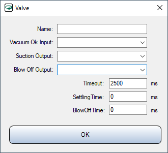
- Name
Display name of the suction cup
- Vacuum Ok Input
Input bit for the state of the vacuum
- Suction Output
Output bit for activating the vacuum cup
- Blow Off Output
Output bit for the blow-off pulse
- Timeout
After setting Suction Output, Vacuum Ok Input must be present within this time
- SettlingTime
Settling time waited after disabling Suction Output and BlowOffTime.
- BlowOffTime
Duration of the blow-off pulse