SVS Vistek
Before using a SVS Vistek camera, the ‘SVCam_GigE_Kit_v1.5.8_Setup_x64_Win’ must be installed. On all LAN adapters with SVS Vistek camera, the ‘SVGigE Filterdriver’ must be activated.
General settings
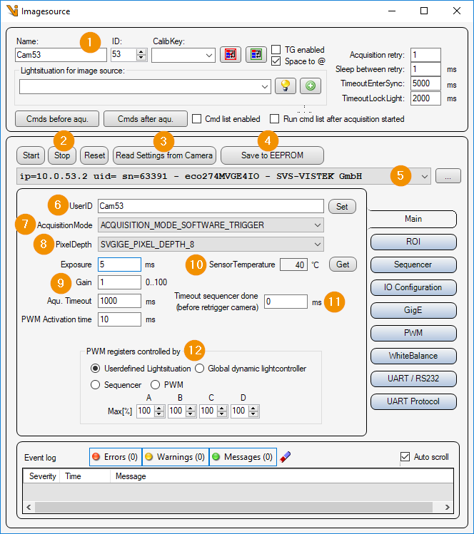
General Settings: Image Source Editor
Start/Stop/Reset
Start: Start camera and prepare for image acquisition.
Stop: Stop camera and exit image acquisition mode.
Reset: Reset all camera parameters to factory settings.
Read Settings from Camera: Read all parameters from the camera and assign them to this image source or image acquisition parameter set.
Save to EEPROM: Save current parameters to the camera’s EEPROM.
Camera list: Selection list of all SVS-Vistek cameras. The list can be updated with the ‘… - button’ to update the list.
User ID: Camera name, which is stored in the camera by clicking on the button ‘set’.
AcquisitionMode: Image acquisition mode or trigger mode. One of the following trigger sources can be selected:
ACQUISITION_MODE_FIXED_FREQUENCY: Permanent image acquisition with fixed frequency.
ACQUISITION_MODE_SOFTWARE_TRIGGER: Software trigger, triggered by Viper.NET during image acquisition.
ACQUISITION_MODE_EXT_TRIGGER_INT_EXPOSURE: Hardware trigger at input.
ACQUISITION_MODE_EXT_TRIGGER_EXT_EXPOSURE: Hardware trigger at input and exposure time externally via input.
PixelDepth: Pixel format in which the camera image is to be transmitted. Depending on the camera type, the following pixel formats can be set:
SVGIGE_PIXEL_DEPTH_8: Image with 8 bits per pixel
SVGIGE_PIXEL_DEPTH_12: Image with 12 bits per pixel
SVGIGE_PIXEL_DEPTH_16: Image with 16 bits per pixel
Image acquisition
Exposure: Exposure time in [ms].
Gain: Analog gain factor (brightness).
Aqu. timeout: Maximum image acquisition time in [ms].
PWM Activation time: Waiting time in [ms] after changing PWM parameters.
Sensor temperature: Value of the temperature sensor of the camera in [°C]. With ‘Get’ the current temperature value is read out from the camera.
Timeout sequencer done: In sequencer mode, all images may have been received before the sequencer is completed in the camera. Before starting the sequencer again, you have to wait for the ‘Sequencer done’ signal from the camera. signal from the camera before restarting the sequencer.
PWM registers controlled by:
User Defined Lightsituation: The PWM outputs of the camera are exclusively available to this image source as light channels.
Global dynamic lightcontroller: The camera registers as a ‘dynamic light controller’ with the Lumos. Thus the PWM outputs of the camera are available as light channels. See also Dynamic LightController.
Sequencer: The PWM outputs are used in the camera’s sequencer.
PWM: The PWM outputs of the camera are set manually on the tab ‘PWM’.
Max[%]A/B/C/D: Maximum brightness value of a PWM output as light channel (’Userdefined Lightsituation’ or ‘Global dynamic lightcontroller’).
ROI settings
Here, an image section (ROI = Region Of Interest) can be set. This means that the entire camera chip is no longer read out and transmitted.
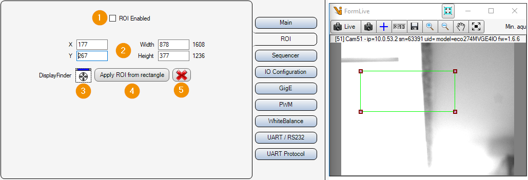
ROI Enabled: Enable or disable image cropping. If deactivated, the entire camera chip is read out and transmitted.
X/Y/Widht/Height: Selected image area. Position of the upper left corner, width and height.
DisplayFinder: With the display finder, a Cognex display (e.g. FormLive) can be selected via drag & drop, which is used for an interactive input of the image section.
Apply ROI from rectangle: Apply image section from rectangle of interactive input.
Cancel: Cancel interactive image selection (remove rectangle from display).
Sequencer settings
The camera has a sequencer that can be used to take several images in succession in a time-optimized manner. For each image, the exposure time, the gain and the assignment of the user outputs can be set. The first image of the sequencer is always assigned to this image source. The remaining images must be connected in Viper.NET via slave image sources.
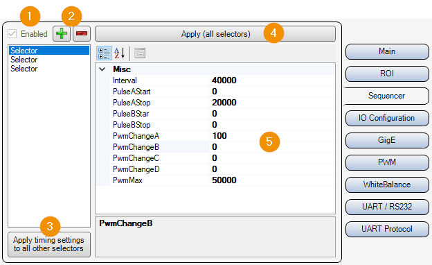
Enabled: Enable/disable sequencer.
+/-: Add or remove image acquisition to the sequencer.
Apply timing settings to all other selectors: Apply the parameters Interval, PulseAStart, PulseAStop, PulseBStart, PulseBStop, PwmMax of the selected selector to all others.
Apply: Write sequencer parameters to the camera.
Selector Parameters:
Interval: Total duration of the sequence step in [µs]. At least the exposure time + image transfer time should be set here.
PulseAStart: Start of the exposure in [µs].
PulseAStop: End of exposure in [µs].
PulseBStart: In Viper.NET always ‘0’.
PulseBStop: In Viper.NET always ‘0’.
PwmChangeA/B/C/D: Duty cycle of on to off time of the PWM outputs in [%].
PwmMax: Maximum PWM frequency.
Inputs Outputs
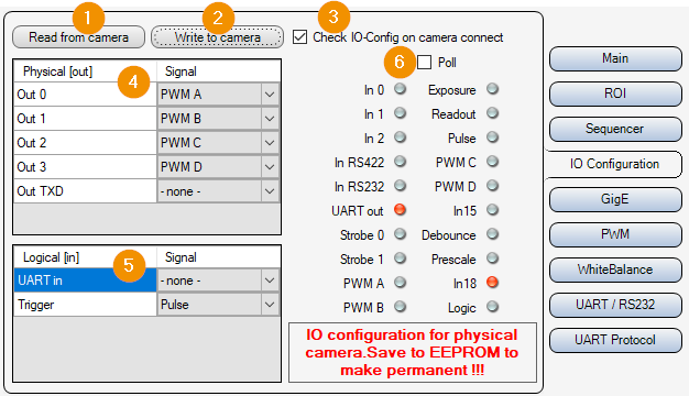
Read from Camera: Read input/output settings from camera.
Write to Camera: Write input/output settings to camera.
Check IO-Config on camera connect: Apply the input/output settings directly after connecting to the camera.
Physical [out]: List of physical outputs. Here you can set which signal of the camera switches the corresponding output.
Logical [in]: List of logical inputs. Here you set which physical input signal is used for which logical signal. (For example input ‘In 0 -> Trigger’)
Poll: Activates the cyclic readout and display of the inputs/outputs.
Gigabit Ethernet Settings
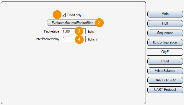
Read only:
On : The parameters are only read out and displayed, but not changed.
Off : The parameters can be set and changed.
EvaluateMaximumPacketSize: Determine maximum packet size for TCP/UDP communication.
Packetsize: Packet size in [byte] for the transmission of the UDP packets of the image data.
InterPacketdelay: Waiting time in [Ticks : Converted time in [µs] is displayed next to the input field] between sending individual UDP data packets of the image data. This slows down the image data transmission and avoids possible data packet collisions or an “overrun” of the LAN adapter or the PC.
PWM settings
The outputs of the camera can be assigned a fixed frequency when activated. For this purpose, you can set the frequency of the signal at the output in [Hz] and the ratio between on and off time in [%].
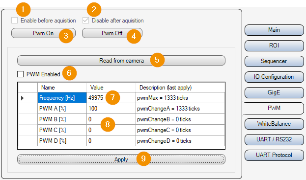
Enable before acquisition: If ‘PWM Enabled’ is active, the PWM outputs are switched on before image acquisition.
Disable after acquisition: If ‘Enable before acquisition’ is active, the PWM outputs are switched off again after image acquisition.
Pwm On: Switch on PWM outputs.
Pwm Off: Switch off PWM outputs.
Read from camera: Read PWM parameters from camera.
PWM Enabled: Write PWM parameters to the camera before image acquisition.
Frequency: PWM frequency in [Hz]
PWM A/B/C/D Dutycycle: Duty cycle between on and off time in [%].
Apply: Apply PWM settings.
White balance
With color cameras, it may be necessary to perform a white balance. This adjusts the gain of each of the camera’s color channels so that the colors are displayed correctly. With Auto White Balance, the camera should be looking at a gray area.
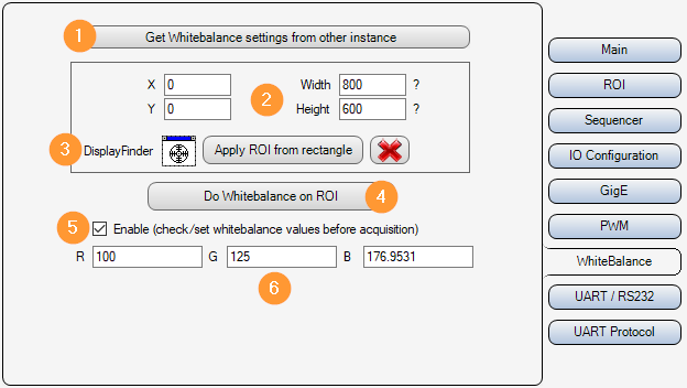
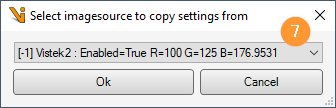
Get Whitebalance settings from other instance: A selection dialog (7) is used to select an SVS-Vistek image source from which the white balance parameters should be copied.
X/Y/Width/Height: Image section in which the automatic white balance is to be carried out.
Interactive image section selection: With the DisplayFinder a display can be selected by drag&drop for the interactive adjustment of the image section for the white balance. A rectangle is then shown in this display. Apply ROI from rectangle then adopts this rectangle as the image section.
Do Whitebalance on ROI: Perform automatic white balance.
Enable:
Off: The set gain factors for the color channels are ignored.
On: The set gain factors for the color channels are used.
R/G/B: Gain factors for the individual color channels.
UART/RS232
The camera has a built-in UART (Universal Asynchronous Receiver Transmitter). This allows you to communicate with an external device via RS232. For this purpose, ‘Out TXD’ must be set to ‘UART out*’ and ‘UART in’ must be set to ‘RS232’ in the input/output settings.
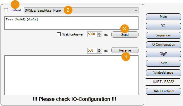
Enabled: If active, the UART parameters are written to the camera and data can be sent and received.
BaudRate: Baud rate for the UART, i.e. how many characters are transmitted per second. Value range: [110..115200] Baud.
Send: Send data from the text field.
Receive: Receive data (read from UART into buffer) and display in text field.
UART Protocol
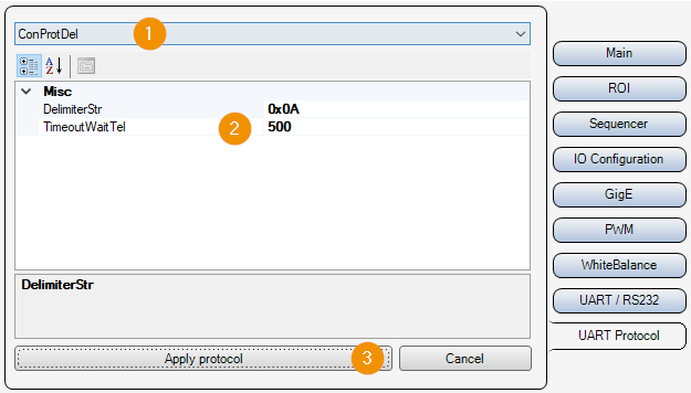
So that the input data can be broken down into telegrams, a protocol (1) must be selected and parameterized (2).
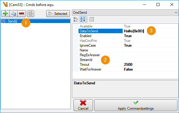
If the UART is enabled and a protocol is set, it can be used to communicate with an RS232 device in a ‘command before image acquisition’. The UART of the camera is used if the parameter (2) ‘StreamId’ is not set.