Toolgroup Item Editor
The ToolGroup Item editor is used to edit the image processing workflow in the form of ToolGroups and all associated settings. The editor can be accessed via the Job editor or via shortcuts, for example the button for editing the currently active toolgroup item ![]() in the Job-Display Toolbar.
in the Job-Display Toolbar.
Toolgroup
Editing a toolgroup is done in an editor from Cognex VisionPro. The description of the User interface is limited to essential elements. A detailed description can be found in the Cognex Help (see Toolbar).
Warning
Changes to the tool group influence the evaluation and should therefore only be carried out if sufficient expertise is available!
Even renaming tools can change the system behavior!
Within Viper.NET, certain modules in ToolGroups get special functions. For example, results of a Tool of Viper.NET can be displayed elsewhere or configuration options for saving images can be adjusted. Only by conformity of the Toolgroup with the conventions of Viper.NET compatibility and functionality are guaranteed.
User interface
The default view of the ToolGroup Editor consists of:
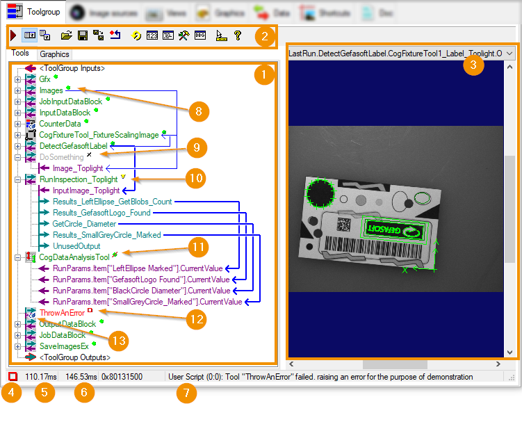
Tool panel to edit the ToolGroup flow.
Toolbar with editing functions
Display for viewing available visualizations of the included tools. The graphic to be displayed can be selected in the dropdown. The display can be enabled/disabled in the Toolbar.
Status bar with information about the last execution.
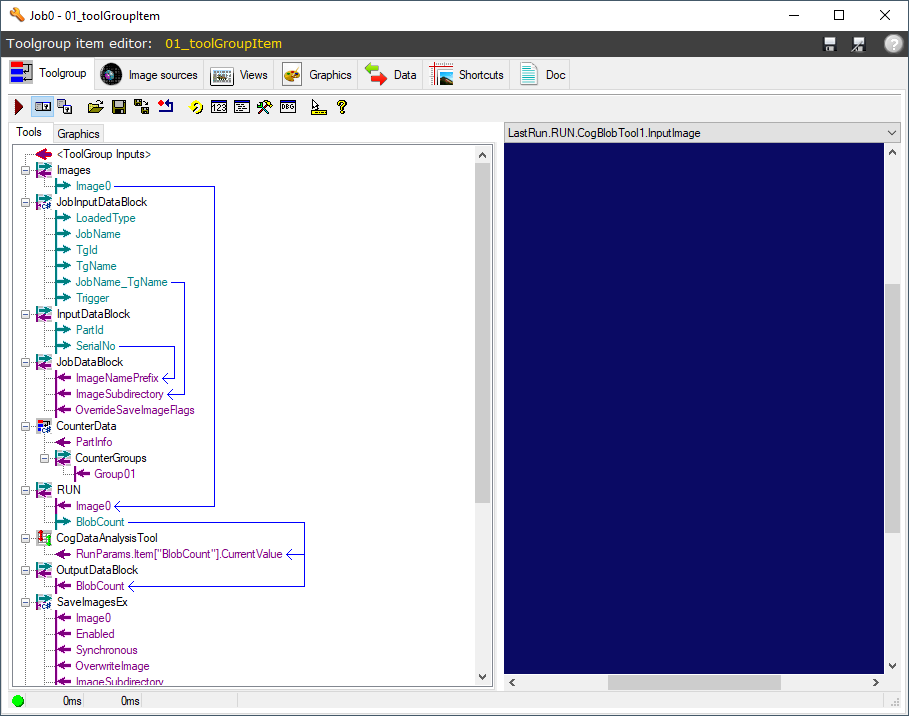
tool panel
The Tool Panel (1) shows contained Vision tools as well as subordinate ToolGroups and ToolBlocks. Arrows visualize the connections from output to input terminals between tools.
Editing the sequence list is mainly done via context menu and drag-and-drop as well as in the Toolbar. In particular, the list of available tools can be opened there. The setting of individual tools is done in a separate window, which is opened by double-clicking on the tool.
Each tool is represented with an icon and its unique name. The display of each tool can be expanded or reduced so that the individual input/output terminals become visible. (Plus/minus icon or Collapse all in the context menu). If the toolgroup has already been executed, an icon to the right of the name visualizes the status of the last tool execution (cf. image):
A tool with IO status. The display of the connected terminals is reduced.
A disabled tool will not be executed and has no available status.
A tool with warning status and superimposed terminals.
A tool with NIO status
A tool with error status
If the icon of tool blocks or tool groups is overlaid by a C# icon (13), the block contains a user script. Scripts can be used to implement almost any function in a module. The execution of contained tools can also be controlled: For example, the execution of individual tools can be skipped.
Hint
If an error occurs during the execution of a tool (status error), the execution of the containing tool group is aborted. The status and results of the subsequent tools are then not updated and show values of tool group executions that have already been executed for a longer period of time.
Status bar
The status bar of the ToolGroup window displays information about the last execution of the toolgroup (see Figure):
Status of the last execution as icon
Execution time exclusive of the generation of visualizations
Total execution time including the generation of visualizations
Status message. In particular, an error message is usually displayed if one occurred.
Toolbar
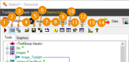
Executes the toolgroup with the last input data. Execution is limited to the toolgroup: neither upstream nor downstream Viper.NET functions are executed. For example, there is no image acquisition from image sources, no updating of displays and no forwarding of result data to hardware.
Enables/disables the display of the local display window for images and result overlays of the ToolGroup on the right side.
Opens a separate display window for images and result overlays
Loads a saved ToolGroup (Vpp file). The current ToolGroup will be replaced!
Saves the ToolGroup
Saves the ToolGroup to any file (Export)
Deletes all existing tools
Executes the toolgroup repeatedly in a loop. Execution is limited to the toolgroup and takes place with the last input data. Upstream and downstream Viper.NET functions are not executed.
Opens an overview of the results of individual tools
Opens the script editor for editing ToolGroup scripts.
Opens the tool window for adding new tools
Opens the Object-Editor from Cognex with expert settings for the ToolGroup
Enables/Disables Tool Tips
Opens the Cognex Help
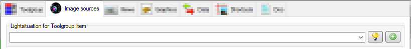
Image sources
The Image sources tab manages the image sources that provide the input images for the ToolgroupItem.
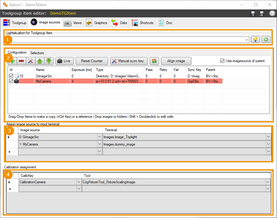
Light situation for the toolgroup’s image input, if it is not defined by the image sources themselves
Image source assignment to input images
Assignment of calibrations when using the global calibrations
Image sources Definition
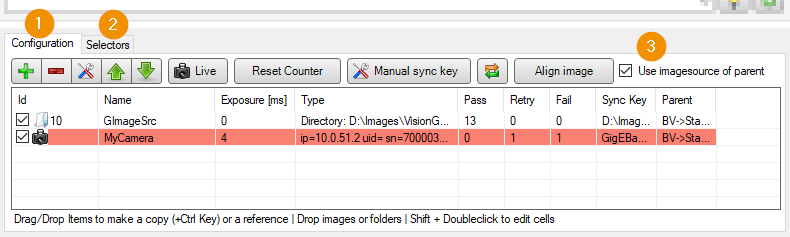
Configuration: Configuration of relevant image sources in the form of a image-source-list.
Selectors: Setting Image Source Selectors: Selectors can be used to dynamically adjust the sources of reference image sources when triggering the toolgroup item.
Use imagesource of parent: If this option is active, the image source list of the job level is displayed and used. Changes to the list then also affect all other toolgroup items that use it! If the option is inactive, the image source list is defined exclusively for the toolgroup item.
Warning
Changes to the order of the image sources in the list will change the image source assignment!
Warning
If the image source list of the job is used, it will be edited directly. Changes to the list can influence the behavior of other toolgroups!
Lighting situation
The toolgroup item can optionally define its own light situation. This is then activated for the duration of the image acquisition of all active image sources.
The selection and configuration of a lighting situation is analogous to the setting of light situation of an image source.
Warning
If a lighting situation is defined for the toolgroup item, the image sources used must not contain their own lighting situation.
Image sources Assignment
Each terminal of a ImagesToolBlock can have exactly one image source associated with it. When triggering the tool-group-item with image-source, Viper.NET sets the image of the respective source as value of the output terminal.
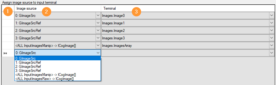
Each line defines an associated terminal and image source pair:
Edit: The blank column is used to mark an assignment row. A marked line can be deleted by pressing the Remove key.
Image source: Selection of the image source providing the data. The mapping is defined in terms of the index in the defined list, counting from 0. The display text shows the index and the name of the active source.
The index and name of the image source are displayed:
0..N : image source name: Single manipulated-image -> ICogImage Terminal.
<ALL InputImagesManip>: All manipulated images of the image source list -> ICogImage array terminal.
<ALL InputImagesRaw>: All raw images in the image source list -> ICogImage array terminal.
Terminal: Selection of an output terminal of the ImagesToolBlock of the ToolGroup.
The empty line at the end of the list creates a new assignment pair as soon as the user defines one of the columns by list selection.
Assignment of calibrations
In ToolgroupItems that use global calibrations, a calibration must be assigned to each calibration tool in the sequence.
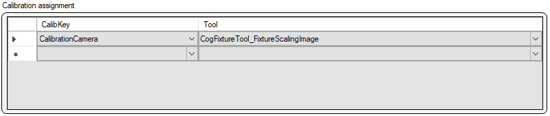
Each line defines a pair of assignments:
Edit: The blank column is used to mark an assignment row. A marked line can be deleted by pressing the Remove key.
CalibKey: Calibration key to identify the global calibration
Tool: Name of the calibration tool in the toolgroup run.
The empty line at the end of the list creates a new assignment pair as soon as the user defines one of the columns by list selection.
Image Source Selectors
Reference image sources in ToolgroupItems can dynamically select between parent image sources based on the values of GInOut variables. To do this, at least one reference-image-source must be defined in the ToolgroupItem. The dynamically referenced sources in turn must be defined in a suitable place with unique ID.
The selection criteria are set in the Selectors tab:
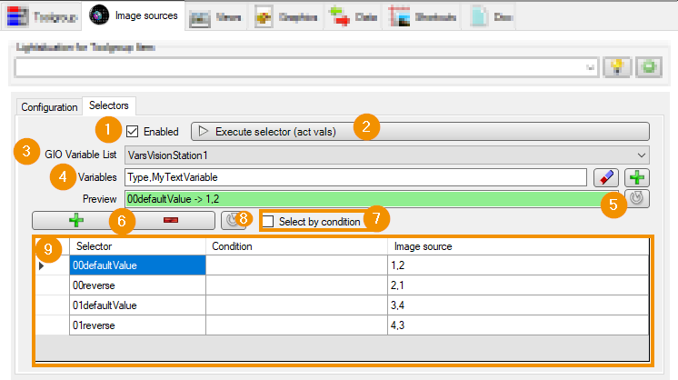
Enabled: (Dis)enables the dynamic selection of the reference source.
Execute Selector: Suspends the referenced image sources based on the current values of the GInOut variables without starting the job.
GIO Variable List: Selection of a variable list containing the hardware variables.
Variables: Names of GIO variables whose values are decisive for the selection. They are specified as comma-separated lists. The buttons can be used to add variables by list selection or to remove invalid variables. Invalid variables are those that are not contained in the set variable list.
Preview: On button click, shows the currently applicable selector in the form
<selector name> -> <ID of selected image source>. In the image, the value of the variable ‘Type’=’00’ and the value of the variable ‘MyTextVariable’=’defaultValue’. Therefore the selector with the name ‘00defaultValue’ works and the image sources with IDs ‘1’ and ‘2’ are selected. If no matching selector is found, the field red appears with an error message.+ -: Add/remove an entry in the List of image source selectors (9).
Select by condition: Specifies whether the decision to select a selector is based on a logical condition:
Off: Image sources are selected based on the selector names: The text values of the individual variables are seamlessly appended to each other. If the text value of the variable corresponds to the name of the selector, the corresponding image source IDs are selected.
On: The ToolGroupItem is selected based on the Condition of the selectors. The numeric values of the variables are inserted into the condition equation equation. The list of equations, or conditions, is processed from top to bottom. If the result of a condition is True (not equal to ‘0.0’), the corresponding image sources are selected.
Refresh: Updates the list of image source selectors
List of image source selectors: The buttons create or remove list entries. Each line in the list defines a condition and the image sources to select if it applies.
Selector: Unique selector name.
Condition: Logical equation for the selection condition. It must be specified exactly if Select by condition is active. It may contain the names of the selected variables, decimal numbers, comparison operators, parentheses and logical operators.
Image source: IDs of the image sources that will be used if the selector matches. The specification is made as a comma-separated list if multiple image sources are to be selected. The number of IDs must match the number of reference image sources of the toolgroup.
Example for Select by condition:
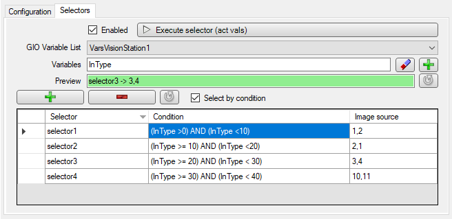
If Select by condition (1) is selected, the values of the variables (2) are inserted into the equations (3). If the result of the equation is not 0.0, the corresponding ToolGroupItem is selected. In the following example, the value of the variable ‘InType’=’27’:
selector1 : (27 > 0 ) AND (27 < 10) : NO
selector2 : (27 >= 10 ) AND (27 < 20) : NO
selector3 : (27 >= 20 ) AND (27 < 30) : YES
selector4 : (27 >= 30 ) AND (27 < 40) : NO
Since selector3 has the first condition met, it becomes active and the image source IDs are set accordingly.
Hint
Multiple overlapping selector conditions should be avoided, but are allowed. For image source selection, the first matching selector in the list is used.
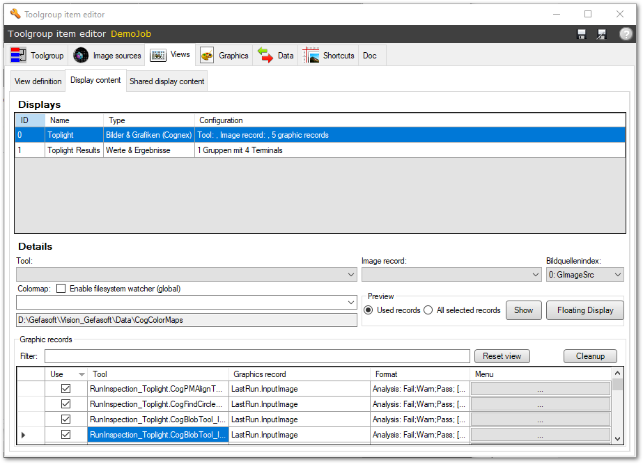
Views
In the Views tab, the Configuration of views is done: Each ToolgroupItem defined an individual View with SubDisplays, which is displayed in the Job-Display after execution. The SubDisplays can display, for example, input and output data, images with overlay graphics or diagrams.
Graphics
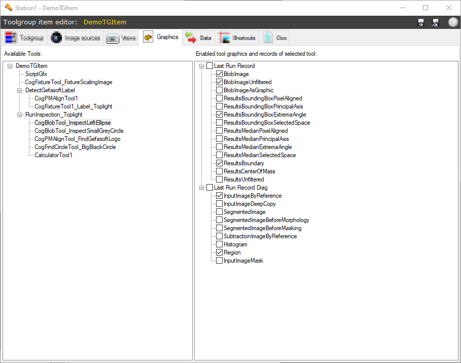
The tab provides simplified access to control which graphics are generated by the VisionPro tools. On the left side, all tools of the ToolGroup are displayed. After selecting a tool, a list of the records and graphics that can be enabled/disabled and that can be generated by the respective tool appears on the right-hand side.
Note
This is a shortcut that is not supported by all tools. The settings can also be made directly in the respective VisionPro tool.
Warning
The creation of graphics requires system resources. Therefore, caution is advised here for time-critical applications!
Data
ToolgroupItems exchange input and result data with external hardware by associating GInOut variables or data ranges with toolblock terminals. The mapping is done in the Data tab of the Toolgroup Item editor. The Input and result data section explains the configuration.
Shortcuts
Important tools of a toolgroup can be displayed as shortcut in the BV Settings (Operator view). This can be used to quickly access tools that need to be edited, for example, for teaching during BV setup or after part adjustments. The configuration is done in the Shortcuts tab of the Toolgroup Item editor.
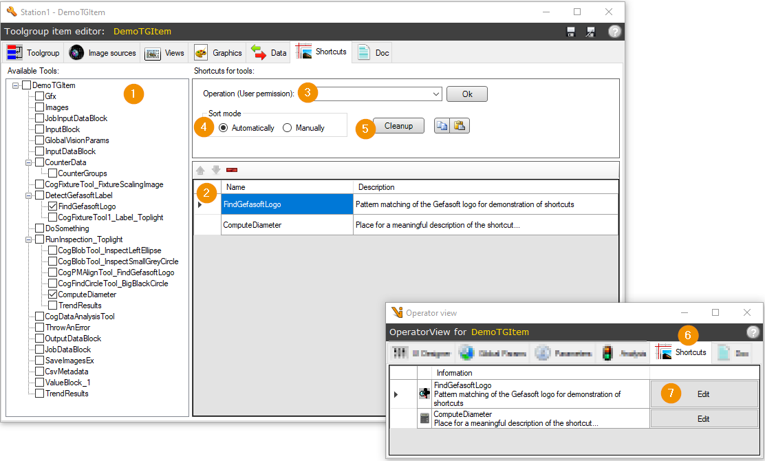
The Tool Tree displays all available tools of the toolgroup, structured according to the ToolGroup/ToolBlock hierarchy. By activating the checkbox of a tool, it is added to the shortcut list (2).
The Shortcut List lists all active shortcuts. A description can be set for each, which is displayed in the BV Settings (Operator view).
With Operation (User permission) a required permission can be set to restrict the accessibility of Shortcuts to authorized Users.
The Sort mode defines the sorting of the Shortcuts: Automatically sorts the entries automatically according to their order within the toolgroup. With Manually an arbitrary order is defined manually.
The Cleanup button cleans up the Shortcut list: it deletes shortcuts that point to non-existent tools.
The Shortcuts tab of the BV Settings (Operator view) shows the configured Shortcuts with the tool name and description.
The Edit button opens the Tool Editor of the respective tool.
Warning
Tools are linked based on the tool name. Renaming tools can therefore create invalid links.
Documentation
The function of the toolgroup can be documented within the toolgroup item. The documentation contains one entry per tool, which can be hidden (in the sense of hidden). The documentation is displayed in the Doc tab of the BV Settings (Operator view) and in the Doc tab of the Toolgroup Item editor. It is also edited or created in the latter.
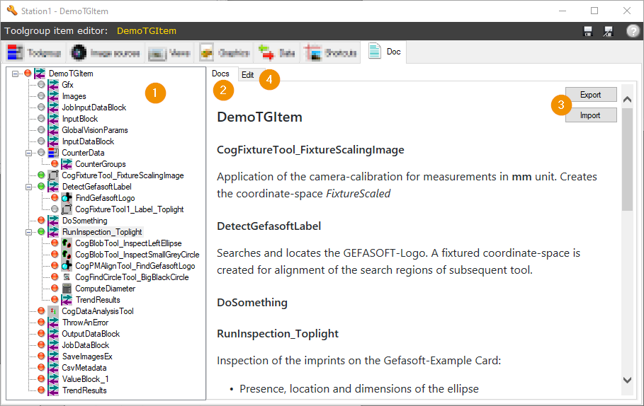
The Tool Tree shows all included tools of the toolgroup. The color of the icon to the left of the tool name shows the respective documentation status of the tool:
A grey icon indicates that the tool documentation is hidden.
A green icon indicates that the documentation for the tool is stored and visible.
A red icon indicates that the documentation for the tool is not filled in but is visible.
In the Tab Docs the documentation is displayed. The heading structure follows the structure of the toolgroup: visible sections for the individual tools appear in the same order as within the toolgroup.
The Export button allows the export of the documentation. Via Import, documentation can be loaded in valid XML format. This allows, for example, documentation to be created by the developer for internationalization and then the translated version to be imported in the local language.
The documentation is edited in the Edit tab. The section of the tool that is currently selected in the Tool tree on the left is edited.
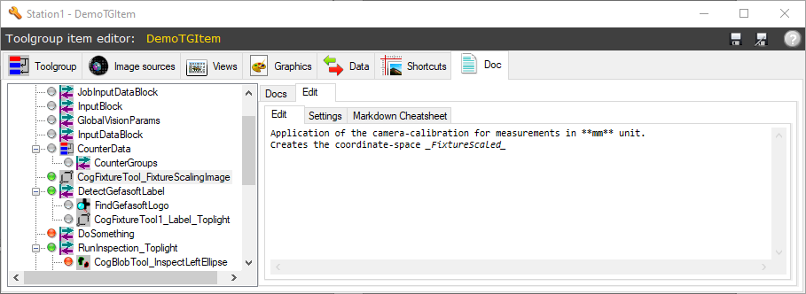
In the editor, the documentation for the selected tool is edited in text form. Text formatting is done using markdown syntax.
In the Settings tab, the Hide doc option can be used to hide the section for the selected tool. It will then not appear in the full text documentation. The icon in the tool tree becomes grey.
The Markdown Cheatsheet describes common text formatting of the Markdown syntax.
Extensions
In the Extensions tab, additional settings are displayed in the case of specialized ToolgroupItems: Additional functions of ToolgroupItems are configured here, which are added by plugins as extensions. An example is the Calibration Toolgroup Item, which includes the configuration of a user interface for result confirmation in this tab.
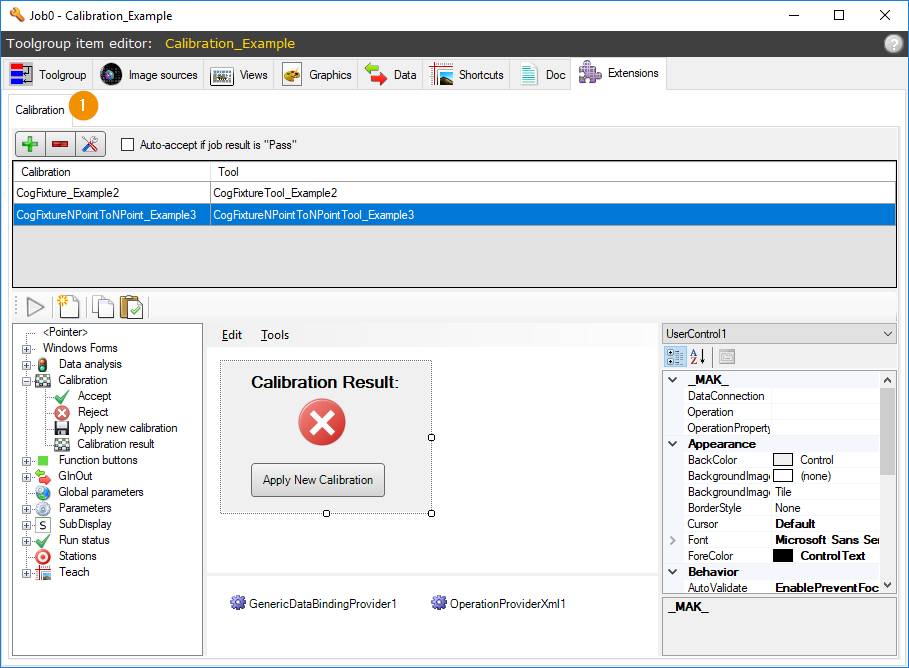
The tab Extensions can in turn contain several tabs for different plugin functionalities (1). For standard ToolgroupItems without any extensions, the tab is not visible.