Fixture3DTool
The Fixture3D tool is used to create new 3D coordinate spaces when processing CogImage16Range images (2.5D), for example for part tracking. Input of the tool can be several Cognex images. Minimum required is a RangeImage of type CogImage16Range.
Functionality
Creation of the new 3D space
The tool creates a new 3D coordinate space relative to the selected space of the input image by concatenating two transformations and appending them to the coordinate tree:
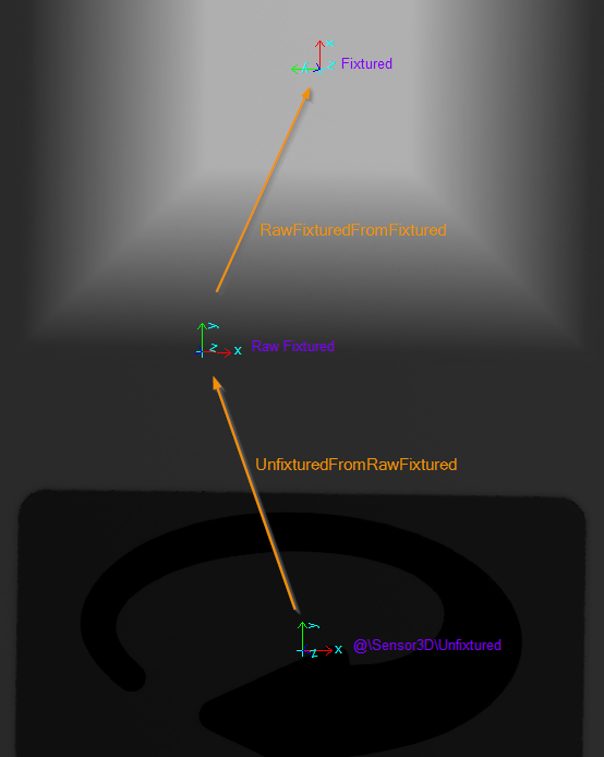
Transformation chain of a fixation with matched output space: the fixed coordinate system is shifted by a constant offset and rotated by 90° with respect to the raw output space of the operator
UnfixturedFromRawFixtured: A selectable Fixture operator dynamically computes a transformation from input data of the tool. In particular, operators are available to define a 3D space using geometric primitives that can be found with 2D operators in the image.
RawFixturedFromFixtured: An additional rigid transformation is appended to the RawFixtured space. This is used in particular to adjust the position of the output space relative to the input primitives: For example, fixed CAD offsets can be incorporated here or coordinate axes can be suitably “swapped” using rotation according to the CAD. A unit matrix is configured as default, so that the output space corresponds to the raw output space of the operator. The transformation can be parameterized in Tool Editor.
Creation of a new 2D space
If necessary, the tool also creates a new 2D coordinate space whose x and y axes lie the image projection of the x and y axes of the new 3D output space.
Warning
A 2D output space should only be created and used as long as its z-axis is “roughly” parallel to the z-axis of the pixel space of the input image. Otherwise, very large coordinate values and possibly numerical problems will arise when displaying and measuring image features.
In general, this projected coordinate system appears with a “skewing of the axes” and an anisotropic scaling. If 2D measurements are made in the image in this coordinate system, the results correspond to those of a measurement within the plane z=0 of the generated 3D system (respectively parallel to it).
Warning
The resulting skewed coordinate spaces can generate [geometric] errors during further processing in other tools, if the tool was not implemented universally applicable. Examples here are tools like CogFindLine, which convert input line segments unchecked under assumption of a rigid transformation between coordinate spaces!
Fixation of related images
In addition to the 2.5D input image, further related input images can be added as input to the tool. The prerequisite is that the coordinate trees of these additional input images refer to the same root space: A copy of each input image is generated as output of the tool (with split pixel data). A new coordinate space is added to the coordinate tree of this output image in such a way that it is located identically to the input images with respect to the tree root. This new space is attached to the selected space of the respective input image.
Tool Editor
General settings
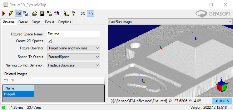
General settings for the operator function are made in the Settings tab of the tool editor:
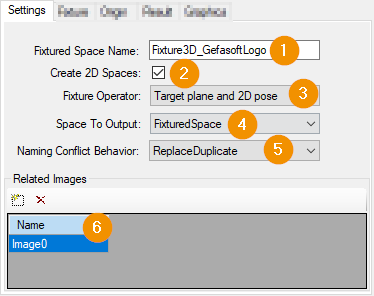
Fixtured Space Name: Naming of the new spaces when inserting them into the coordinate space trees of the output images. The name is used equally for 3D and 2D spaces in all output images.
Create 2D Spaces: If active, adds a new 2D coordinate space to the output images.
Fixture Operator: The selected operator defines the dynamic procedure to create the new 3D space
Space To Output:
FixturedSpace also sets the newly created coordinate spaces as selected coordinate space of the output images enabled.
UnfixturedSpace merely adds the new spaces to the coordinate trees of the output images. As selected space, however, the selected space of the respective input image is taken over unchanged.
Naming Conflict Behavior: Defines the behavior of the tool if a conflict with an existing room of the same name occurs when adding the room:
DuplicateIsError: In case of conflict the tool terminates with an error.
ReplaceDuplicate: The new room should replace the existing one.
IgnoreDuplicate: The existing room will be preserved. The tool skips adding the new room.
Related Images: Here terminals will be created for fixing related additional images.
Origin
In the Origin tab, by parameterizing the RawFixturedFromFixtured transformation, the position and orientation of the output space can be adjusted with respect to the operator result.
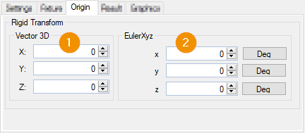
Specifies the displacement of the output system based on the result of the fixture operator.
Specification of the twist with respect to the output system of the fixture operator.
Result
In the Result tab, the transformation unfixturedFromFixtured is displayed as the result of the tool execution:
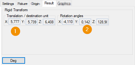
The translation/shift of the output space with respect to the input space. The unit of the translation coordinates is the unit of the output space. for example: If the output space has the unit 1 mm, then the displacement shown is also to be interpreted in mm.
The orientation of the output system compared to the input system. Here given as Euler-XYZ angle.
Graphics
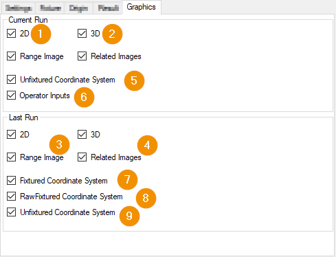
The configuration of the generated graphics is done in the tab Graphics. Here, the combination of the selected options is decisive: Individual graphics can be displayed in up to four records:
Both Roughly, two groups of options can be distinguished:
Options, which records should be created:
2D activates the creation of 2D records for all active visualizations
3D activates the creation of 3D records for all active visualizations
Range Image activates the creation of records for the RangeImage
Related Images activates the creation of records for all additional Related Images
Options that add individual visualizations to all selected records:
Unfixtured Coordinate System: Coordinate system of the selected space of the input image
Operator Inputs: Visualization of geometric input parameters of the fixture operator
Fixtured Coordinate System: Coordinate system of the final generated output space
RawFixtured Coordinate System: Fixture operator output coordinate system (intermediate result without origin adjustment)
Unfixtured Coordinate System: Coordinate system of the selected space of the input image
FixtureOperators
The tool provides several fixture operators that calculate the position of the raw output system based on input data. The input is usually geometric features such as points or lines.
The operators are selected in the Tool Editor in the General Settings
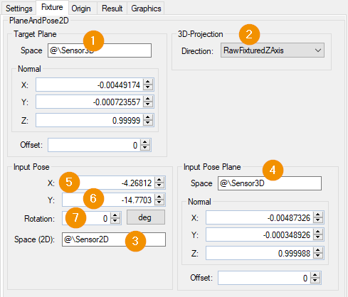
Target Plane and 2D Pose
The operator calculates a new 3D space based on a given 2D target location, a target plane and a projection direction.
A rigid 3D transformation is calculated, which refers to the selected 3D space of the input image. The 2D target plane describes where the projection of the origin and x-axis of the desired raw output space lies relative to a 2D coordinate system on an input plane. The target plane defines the “height” of the output space as well as the orientation of the z-axis of the output space.
Input parameters for the operator are:
Target plane: The xy plane of the raw output space will be in the target plane.
Projection direction: Selection of a direction to project 2D primitives from the input to the target plane
InputPoseSpaceName: Name of the 2D coordinate space to interpret the 2D nominal pose. The space name must be present in the coordinate tree of the input image!
InputPoseSpacePlane: The plane on which the measured primitives of the 2D target layer physically lie.
FixturedOriginX: x-coordinate of the 2D nominal point measured in the InputPoseSpaceName.
FixturedOriginY: y-coordinate of a 2D point measured in the InputPoseSpaceName.
FixturedXAxisRotation: Rotation angle in 2D space describing the desired orientation of the x-axis.
Projection: Projection direction at transition between from input to target plane. Options:
RawFixturedZAxis [Default]: Direction of the z-axis of the raw output space. This corresponds to the normal direction of the target plane
UnfixturedZAxis: Direction of the z-axis of the input space: the SelectedSpace of the input image
Sensor3DZAxis: z-axis of the space named “Sensor3D”
Phys3DZAxis: z-axis of the space named “Phys3D”
The operator calculates the raw output space such that:
The xy-plane of the raw output space lies in the target plane.
The origin of the raw output space from the origin of the input space by perpendicular projection along the projection direction is created.
The direction x-axis of the raw output space is collinear to the projection of the x-axis of the input space. The projection is perpendicular along the projection direction
The orthogonal projection of the output space origin along the projection direction to the xy-direction of the selected input space on the origin of the input plane lies in this plane.
The orthogonal projection of the output space x-axis to the xy-direction of the selected 3D input space the same orientation with respect to the
All input parameters can be adjusted in the editor in the Fixture tab:
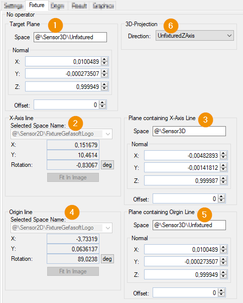
Target Plane and Two Lines
The operator calculates a new 3D space based on a target plane, a projection direction and two lines, namely the XAxisLine and the OriginLine.
A rigid 3D transformation is calculated, which refers to the selected 3D space of the input image. The orientation of the raw output space is given by the target plane and the XAxisLine. Its origin is given by the intersection of the projections of the two lines onto the target plane
TargetPlane: Target plane defining the xy plane of the source system.
XAxisLine: A 2D line defining the direction of the X-axis of the raw output system and a degree of freedom of its origin. The line is interpreted as an image of a 3D line located in the XAxisLineContainingPlane.
XAxisLineContainingPlane: A plane containing the 2D XAxisLine.
OriginLine: A 2D line defining a degree of freedom of the origin of the raw output system. It is interpreted as an image of a 3D line that lies in the OriginLine.
OriginLineContainingPlane: A plane containing the OriginLine.
Projection: Projection direction at the transition between from input to target plane. Analogous to the porjection direction of the Operator TaretPlane and 2D Pose
The 2D input lines together with their respective ContainingPlane each define a line in 3D. The 2D line corresponds to the mapping of a 3D line with the image sensor: the 2D line is the perpendicular projection of the 3D line into the image along the z-axis of the Sensor3D space.
Starting from the 3D input lines, the operator calculates the raw output space such that:
The xy-plane of the raw output space lies in the target plane.
The origin of the raw output system is the intersection of the perpendicular projections of XAxisLine and OriginLine into the target plane along the projection direction
The X-axis of the raw output system is collinear with the perpendicular projection of the XAxisLine into the target plane.
All input parameters can be adjusted in the editor in the Fixture tab:
N-to-N Point on Plane
The operator computes a new 3D space from a list of 2D image points lying on a given input plane and their associated 3D set points.
A rigid 3D transformation is calculated, which refers to the selected 3D space of the input image. The output space is determined as least-squares best-fit in such a way that the input points on the input plane in it receive approximately the desired set coordinates.
The target points can be specified in two ways:
Geometric Fixturing: The design coordinates of the points are entered manually. This creates an output space that replicates the design position of the component as best as possible.
Reference Fixturing: The target point coordinates are taken from a reference image and stored together with it in the tool. This makes it possible to implement simple tracking based on distinctive points for subsequent tools. For example, to define search areas relative to the 3D building position.
Input parameters for the operator are:
Point Correspondence List: A list of corresponding point pairs: UnfixturedX and UnfixturedY are the actual coordinates of the 2D input point, measured in the SelectedSpace (2D) of the input image FixturedX / -Y / -Z are the setpoint coordinates of the respective point in the 3D output space
Input Point Plane: A plane on which all 2D input points are phyiscal. It is used to add the 2D input image points to 3D points, so that the 2D correspond to the sensor mapping of the 3D points into the image.
The mentioned input parameters can be adjusted in the editor in the Fixture tab:
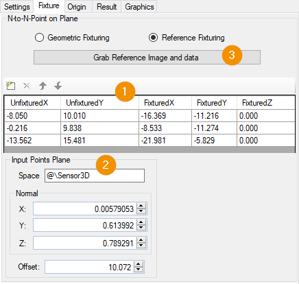
The Grab Reference Image and data (3) button saves the current input data as reference data in Reference Fixturing mode: the input image is taken as reference image, the 3D projections of the unfixtured input image points are saved as fixtured target coordinates.