Baumer
Before using a Baumer camera, the ‘Baumer Software GAPI SDK Win64’ must be installed. The ‘Baumer Filter Driver’ must be activated on all LAN adapters with a Baumer camera.
General settings
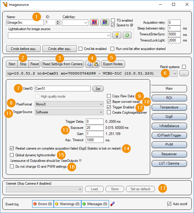
General Settings: Image Source Editor
Start/Stop/Reset
Start: Start camera and prepare for image acquisition.
Stop: Stop camera and exit image acquisition mode.
Reset: Reset all camera parameters to factory settings. This loads the ‘UserSet FactorySettings’.
Read Settings from Camera: Read all parameters from the camera and assign them to this image source or image acquisition parameter set.
Copy/Paste:
Copy: Copy this parameter set to the clipboard.
Paste: Copy the parameter set from the clipboard for this image source.
Export Nodes: Read out all parameters from the connected camera and export them to an XML file.
Camera list: Selection list of all Baumer cameras. The list can be updated with the ‘… - button’ to update the list. If ‘Reinit systems’ is activated, the Baumer systems (GigE and USB3) are reinitialized before searching for Baumer cameras.
UserID: Camera name that is stored in the camera by clicking the button ‘set’.
Pixel format: Pixel format in which the camera image is to be transmitted. Depending on the camera type, the following pixel formats can be set:
Mono8/10/12/14/16 : Gray scale image with 8/10/12/14/16 bits per pixel
BayerRG8/12 : Color image in red-green Bayer pattern with 8/12 bits per pixel.
RGB8 : Color image with red green blue pixels.
YUV422/444 : Not implemented in Viper.NET !
Copy Raw Data: Image data is not converted and is copied as raw data. If deselected, a Bayer image, for example, is converted to an RGB image.
Bayer convert mean: If ‘Copy Raw Data’ is deselected and the pixel format is BayerRG8/12, adjacent pixels are averaged when converting to an RGB image.
TriggerSource: One of the following trigger sources can be selected:
Software : Software trigger, triggered by Viper.NET during image acquisition.
Line0..7 : Hardware trigger at input 0 - 7.
Counter1/2End: Expiration of counter 1 or 2.
Trigger Enabled: If selected, the camera is in trigger mode. An image will not be captured until the trigger is released.
Image acquisition
Trigger Delay: Image acquisition delay in [ms].
Exposure: Exposure time in [ms].
Gain: Analog gain factor (brightness).
Aqu. timeout: Maximum image acquisition time in [ms].
Restart camera on complete acquisition failed: If selected, restarts the camera’s image acquisition mode after an image acquisition failure. (CAUTION: This will also reset the camera’s statistics counters).
Global dynamic lightcontroller: The camera registers as a ‘Dynamic light controller’ with Lumos. This makes the PWM outputs of the camera available as light channels. See also Dynamic LightController.
Do not change IO and PWM settings: The parameter set ignores the input and output parameters as well as the PWM settings.
Userset: Here the user parameter sets stored on the camera can be loaded, or the current settings can be stored in a user parameter set of the camera.
ROI settings
Here, an image section (ROI = Region Of Interest) can be set. This means that the entire camera chip is no longer read out and transmitted.
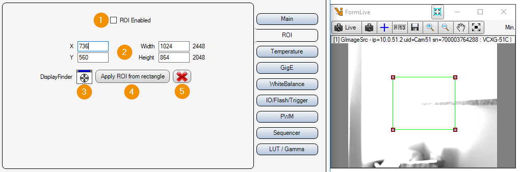
ROI Enabled: Enable or disable image cropping. If deactivated, the entire camera chip is read out and transferred.
X/Y/Widht/Height: Selected image area. Position of the upper left corner, width and height.
DisplayFinder: With the display finder, a Cognex display (e.g. FormLive) can be selected via drag & drop, which is used for an interactive input of the image section.
Apply ROI from rectangle: Apply image section from rectangle of interactive input.
Cancel: Cancel interactive image selection (remove rectangle from display).
Temperature probe
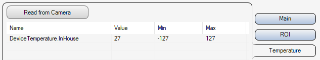
All temperature sensors of the camera are displayed in the list. With ‘Read from Camera’ the temperature values are read out again.
Gigabit Ethernet Settings
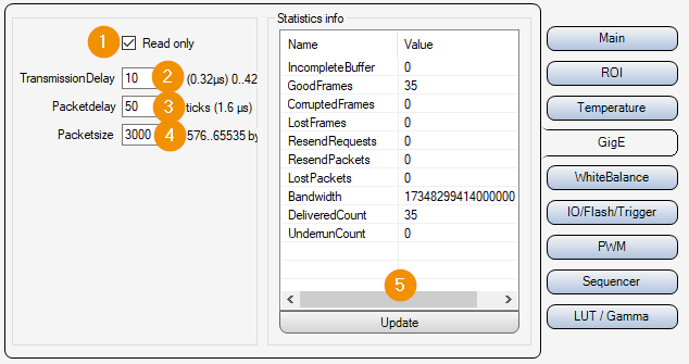
Read only:
On : Parameters 2-4 are only read out and displayed, but not changed.
Off : Parameters 2-4 can be set and changed.
TransmissionDelay: Waiting time [in Ticks : Converted time in [µs] displayed next to the input field] until the camera starts to transmit the image data. If several cameras are triggered at the same time, it can be helpful to set a different delay time for each camera to avoid data packet collisions.
Packet Delay: Waiting time in [ticks : converted time in [µs] is displayed next to the input field] between sending individual UDP data packets of the image data. This slows down the image data transmission and avoids possible data packet collisions or “overrun” of the LAN adapter or the PC.
Packetsize: Packet size in [byte] for the transmission of the UDP packets of the image data.
Statistic info: Data transmission statistics of the camera. With “Update” the statistics are read out and displayed again. ATTENTION: If the parameter “14. Restart camera on complete acquisition failed” is activated in the tab “Main”, the statistics will be reset automatically in case of an error.
White balance
With color cameras, it may be necessary to perform a white balance. This adjusts the gain of each of the camera’s color channels so that the colors are displayed correctly. With Auto White Balance, the camera should be looking at a gray area.
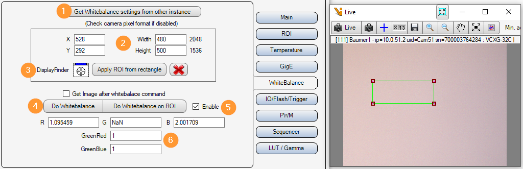
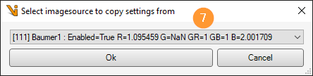
Get white balance settings from other instance: A selection dialog (7) is used to select a Baumer image source from which the white balance parameters are to be taken.
X/Y/Width/Height: Image section in which the automatic white balance is to be carried out.
Interactive image section selection: With the DisplayFinder a display can be selected by drag&drop for the interactive adjustment of the image section for the white balance. A rectangle is then shown in this display. Apply ROI from rectangle then adopts this rectangle as the image section.
Do Whitebalance on ROI: Perform automatic white balance.
Enable:
Off: The set gain factors for the color channels are ignored.
On: The set gain factors for the color channels are used.
R/G/B/GreenRed/GreenBlue: Gain factors for the individual color channels.
Inputs Outputs
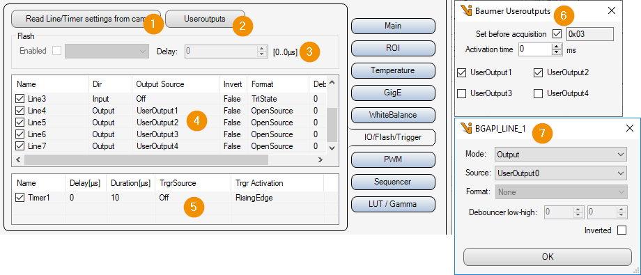
Read Line/Timer settings from cam: Read input/output and timer settings from camera.
Useroutputs: Opens the window for the user outputs (6).
Flash: Enable/disable flash output of the camera. (Only available if the camera has the “Flash” parameter).
Lines list: List of available inputs/outputs. Double-click on an element to open the parameter window for the corresponding input/output (7).
Timer list: List of available timers. Double-click on an element to open the parameter window for the corresponding timer. If the camera’s sequencer mode is active, the timers are used by the sequencer !
User Outputs: Switch user outputs on/off.
Set before acquisition: Set user outputs to the set values before image acquisition.
Activation time: After setting the user outputs, the activation time in [ms] is waited until the image acquisition is triggered.
UserOutput 0..7: Switch the corresponding user output on/off.
Line Setting: Input/output settings of the corresponding “Line” of the list (4)
PWM settings
The outputs of the camera can be assigned a fixed frequency when activated. For this purpose, you can set the on-time of the output in [µs] and the ratio between on-time and off-time in [%]. In order to be able to switch the outputs via the software, they must be linked to the user outputs.
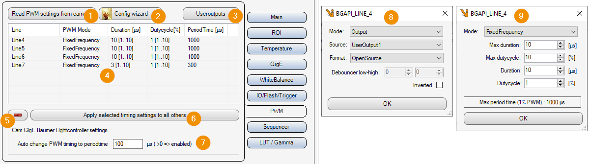
Read PWM settings from cam: Read PWM settings from camera.
Config wizard: Supports the user to set the inputs/outputs and the PWM parameters so that this camera can be used as a Global Light Controller. This requires linking the corresponding outputs to the user outputs and setting the PWM mode to fixed frequency. See also windows 8 and 9.
UserOutputs: Opens the window for the user outputs. See also “Inputs- Outputs -> Useroutputs”.
Output list: List of all outputs and their current PWM parameters. Double click on an element opens the PWM timing parameters (9.).
-: Remove output from the list. This means that no more PWM parameters are written to the camera for the corresponding output.
Apply selected timing settings to all others: Apply the PWM timing settings of the selected output to all other outputs in the list.
Auto change PWM timing to periodtime: The PWM timing parameters are set in such a way that the period duration set here results in [µs].
Output Parameters: This window is opened by the Config wizard (2.) for each output.
PWM timing parameters: This window is opened by the Config wizard (2.) for the first output and the set parameters are then applied to all outputs.
Max duration: Maximum on-time in [µs] for this output.
Max dutycycle: Maximum duty cycle from on to off time in [%].
Duration: Current on-time in [µs] for this output.
Dutycycle: Current duty cycle from on to off time in [%].
Sequencer settings
Die Kamera besitzt einen Sequenzer, über den Zeitoptimiert mehrere Bilder hintereinander aufgenommen werden können. Für jedes Bild lässt sich die Belichtungszeit, die Verstärkung und die Belegung der Benutzerausgänge einstellen. Das erste Bild des Sequenzers wird dabei immer dieser Bildquelle zugeordnet. Die restlichen Bilder müssen in Viper.NET über Slave-Bildquellen angebunden werden.

+/-: Add or remove image acquisition to the sequencer.
Enabled: Enable/disable sequencer.
Force resend on next trigger: The sequencer parameters are written to the camera on the next image acquisition, even if no parameters have changed.
Exposure: Exposure time in [ms].
Gain: Gain factor.
Output1/2/3/4: User output 1-4 Switch on or off.
Gamma correction
Bei der Gammakorrektur werden die Pixelwerte über eine Potenzfunktion umgerechnet. Dadurch können zum Beispiel hellere Bereiche nichtlinear weiter aufgehellt werden.
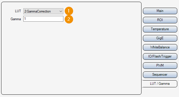
LUT: Activate or deactivate the Look Up Table (LUT).
Gamma: Gamma parameter for generating the correction table.