HalconWrapperTool
The tool integrates the HDevelop engine from the Halcon image processing library by MVTec into VisionPro. A HalconWrapperTool implements the call of a Halcon procedure as a VisionPro tool. The interface parameters of the procedures are included as tool terminals. If required, a semi-automatic conversion between Halcon and VisionPro data types is performed: Parameters can be exchanged between Halcon tools as Halcon data types, for interoperability with Vision-Pro tools the parameters have to be converted.
Preparing the procedure
To make procedure parameters available as terminals in the HalconWrapperTool, the parameter documentation of the procedure must be sufficiently filled in HDevelop: For all required parameters, especially all input parameters, at least the semantics of the parameter must always be documented. If a conversion of the parameter to VisionPro/system data types is to take place, additional information must be provided, which is listed below for the individual parameter types.
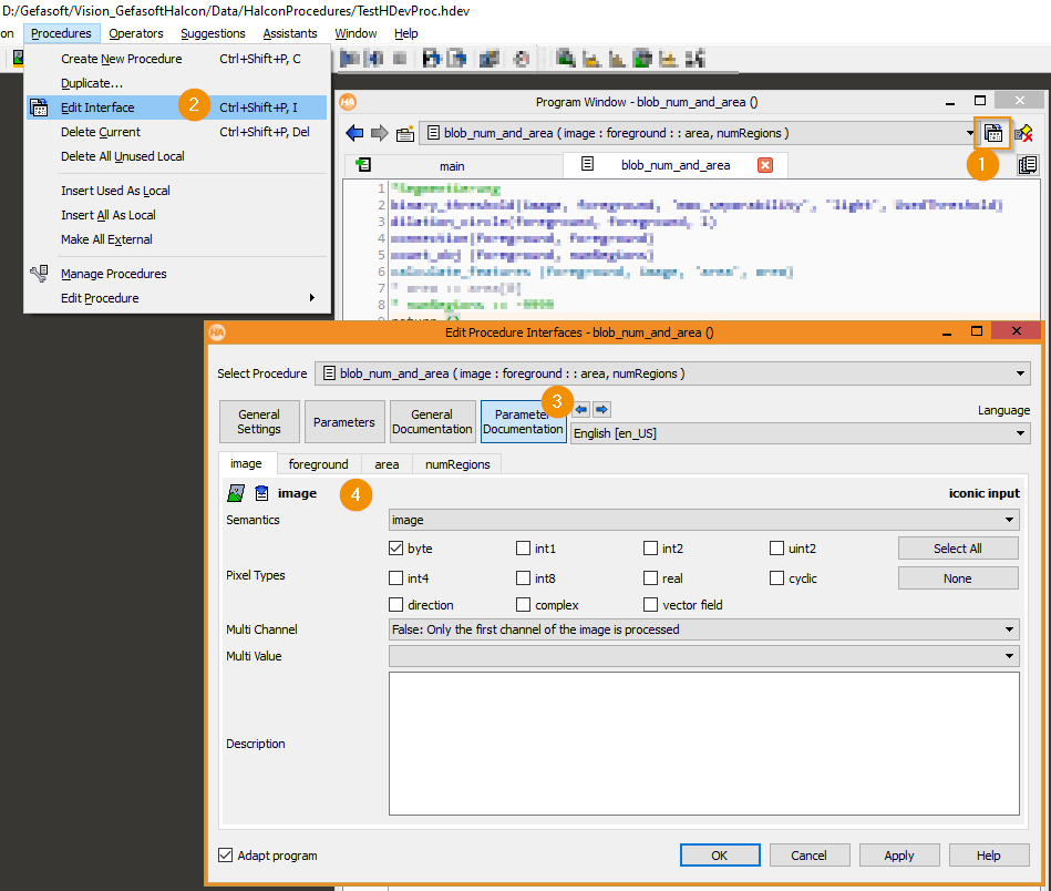
Opening the Procedure Interface Setting in the HDevelop Script Editor
Open the Procedure Interface setting in the HDevelop menu bar.
Documentation of the procedure parameters in the interface settings
Editing the documentation of individual procedure parameters, for example an image parameter
Images
The wrapper tool creates terminals with the prefix InputImage or OutputImage for documented input and output images. For this purpose, at least the semantics image must always be set in the parameter documentation. With complete documentation, conversion from and to Cognex image types is supported for the following types:
Cognex type |
Semantics |
Pixel types |
Multichannel |
Multiple values |
|---|---|---|---|---|
CogImage8Grey |
image |
byte |
No |
No |
CogImage16Grey |
image |
uint2 |
No |
No |
CogImage24GreyColor |
image |
byte |
Yes (3) |
No |
Hint
If several Halcon wrapper tools use the same input image, it is recommended to use a HalconCognexConverterTool to convert the Cognex image into a Halcon image. By having the HalconWrapperTools receive the image directly as Halcon input, time is saved for redundant conversions.
Regions
The wrapper tool creates terminals with the prefix InputRegions or OutputRegions for documented input and output regions. For this purpose, at least the semantics region must always be set in the parameter documentation of the procedure. When converting from and to Cognex types, a distinction must be made between input and output terminals. It is supported with the following additional specifications in the parameter documentation:
Cognex type input terminal |
Semantics |
Multiple values |
|---|---|---|
CogCircle
CogEllipse
CogRectangle
CogRectangleAffine
CogLineSegment
CogPolygon
|
region |
No |
Cognex type output terminal |
Semantics |
Multiple values |
|---|---|---|
CogPolygon |
region |
No |
Hint
Halcon regions define pixel-precise faces, while geometric primitives define subpixel-precise faces. The conversion produces the best approximation using the most specific operator call possible, for example gen_circle. Output regions are always approximated as polygons. The approximation is done with the Halcon operator get_region_polygon, with tolerance 0.01 pixels.
Warning
The conversion of output regions to Cognex polygons ignores hollow areas and returns only the hull! Only one context component is returned (usually the first one, see Halcon operator get_region_polygon).
XLDs
For documented input and output XLDs, terminals are created with the prefix OutputXlds or InputXlds. For this purpose, at least the semantics xld must be set in the parameter documentation. The semantics can optionally also be specified with maximum specificity, for example as xld_poly.
Automatic conversion to Cognex data types is not supported for XLDs. A wrapper around the Halcon type is provided at the terminals.
Control parameters / tuples
With the exception of vectors, control parameters can be used as input or output terminals without parameter documentation. However, without specifying the semantics in the parameter documentation, only terminal access as HTuple is possible. Parameters of type HVector are not supported. Terminals are usually created with the prefix InputControlVariables or OutputControlVariables. Exceptions are sufficiently documented parameter types of resources like camera_setup_model, which are for example created with the prefix InputCameraSetupModels. With the following documentation settings, access in the form of the named system types is also possible:
Cognex type |
Semantics |
Type list |
Standard type |
mixed types |
several values |
|---|---|---|---|---|---|
System.Integer |
integer |
integer |
integer |
No |
No |
System.Integer[] |
integer |
integer |
integer |
No |
Yes |
System.Double[] |
real |
real |
real |
No |
No |
System.Double[] |
real |
real |
real |
No |
Yes |
System.String |
string |
byte |
string |
No |
No |
System.String[] |
string |
byte |
string |
No |
Yes |
HTupleOm3Box |
object_model_3d |
- |
- |
- |
- |
HTupleCameraSetupBox |
camera_setup_model |
- |
- |
- |
- |
HTupleCalibModelBox |
calib_data |
- |
- |
- |
- |
Hint
The wrapper objects HTupleOm3Box implement reference counting and automatic resource sharing. As of Halcon 18.11, their use is no longer required unless Halcon mode legacy_handle_mode is enabled (not recommended). With legacy_handle_mode active or with older Halcon versions, the wrapper types should be used to avoid memory leaks. Resources passed to such terminals must and must not be released by the user.
Procedure setting
A tool instance serves as a wrapper around exactly one Halcon procedure. You can load local procedures from a program file (.hdev) as well as global procedures from single procedure files (.hdvp). It is recommended to use local procedures in program files.
Setting and loading procedures is done in the Settings tab of the Tool Editor:
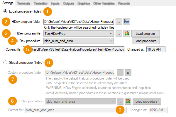
Local procedure (.hdev): defines that the tool loads a local procedure with the specified settings.
HDev program folder: Directory path where the program file (
.hdev) is located. The button supports drag-and-drop. The buttons to the right can be used to select a folder via file browser or to open the selected folder in the browser. Changing the path triggers a reload of the procedure.HDev program file: Selection of a program file (
.hdev) within the program folder from which the procedure is loaded. The buttons on the right can be used to open a file browser for file selection and to update the dropdown list (searches the directory for relevant files). The selected program is loaded only with a button click on Load program.HDev procedure: Selection of the procedure within the loaded program.
Current file and Changed at: Displays the currently loaded program file and the time of loading.
Global procedure (.hdvp): defines that the tool loads a global procedure with the specified settings.
Custom procedure folder: Path containing procedure files (
.hdvp). Changing the path triggers the reloading of the procedure. With the buttons on the right a selection can be made via file browser or the value can be deleted. If no procedure path is set, thenHDev procedure: Procedure name. Listed are the file names within the Custom procedure folder (which by convention match the name of the contained procedure). The buttons on the right can be used to make a selection using the file browser, and to update the drop-down list (in the event of changes to the file system). Only a button click on Load procedure triggers the reloading of the selected procedure, pure changes of the selection do not yet change the tool status.
Current file and Changed at: Displays the name of the currently loaded procedure and the load time.
Terminals
The input and output parameters of a procedure are accessed via tool terminals. When loading a procedure, placeholders for the terminal data are created. The prerequisite for the creation is that the data types of the parameters are sufficiently and correctly defined in the Halcon parameter documentation of the procedure. If the documentation is sufficient, automatic conversions from and to Vision-Pro or system data types can be performed. The necessary documentation entries and supported conversions are described in Preparing the procedure. After successfully loading a procedure, the user can trigger the creation of terminals in the Terminals tab, which refer to the named data structures. It can be specified whether a terminal with Halcon or Cognex data type (or both) should be created.
Hint
If terminals of both types are created for an output parameter, both terminals can be used. For input parameters, however, only one terminal may be connected at a time, even if two can be created (so that the assignment of the input value is unique).
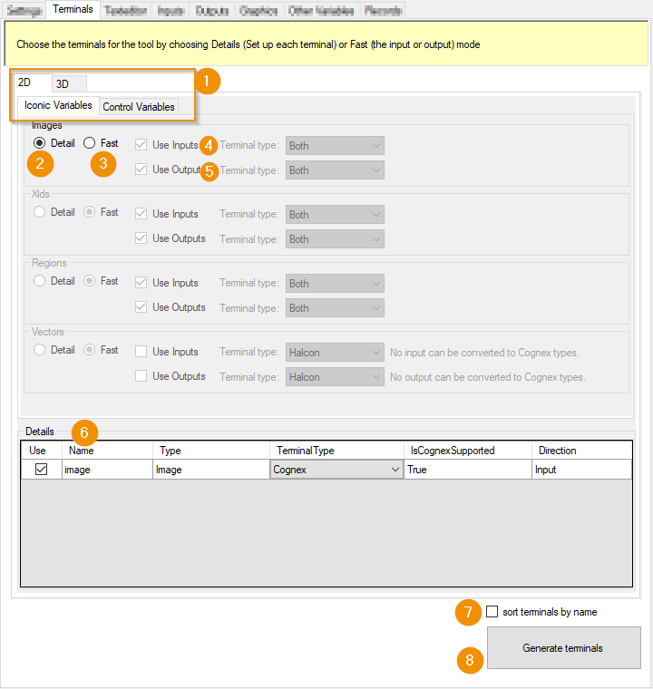
The configuration is structured according to the data types of the parameters.
2D/3D, Iconic Variables/Control Variables: Selection of a parameter category: 3D parameters (ObjectModel3D and CameraSetupModel Handles) or 2D parameters, again subdivided into Iconic and Control parameters.
Detail: The terminals of all procedure parameters of the respective Halcon data type are configured individually. The procedure parameters are added to the configuration in the Details list.
Fast: The terminals of all procedure parameters of the respective Halcon data type are configured generically: The options on the right define the terminals to be created.
Use Inputs: Specifies, when using Fast, whether the terminals should be generated for all input parameters. The Terminal type dropdown defines with which data types the terminals should be created: Halcon types, Cognex types, or Both. The latter creates two terminals for each parameter: one each with Congex and Halcon data types. For input parameters, only one terminal can be connected by the user at a time!
Use Outputs: Specifies, when using Fast, whether the terminals should be generated for all output parameters. The Terminal type dropdown defines with which data types the terminals should be generated: Halcon types, Cognex types, or Both.
Details: A list of procedure parameters whose terminal generation is individually configured based on a Detail setting.
Use: If selected, a terminal is created for the parameter.
Name: Name of the procedure parameter
Type: Halcon type of the parameter
TerminalType: Selection of the type of terminal to be created: Cognex, Halcon or Both.
IsCognexSupported: Indicates whether conversion between Halcon and Cognex data types is possible. If not, either the Halcon parameter documentation is incomplete or a conversion is not supported.
Direction: Procedure parameter type: Input or Output.
sort terminals by name: defines the order of the created terminals. If selected, the terminals are sorted alphabetically by name.
Generate terminals: Triggers the (re)generation of the procedure parameter terminals. Existing parameter terminals that do not match the settings are removed if they do not match the settings.
Text editor tab
In the tab Text Editor the source code of local procedures of the loaded HDevelop script can be displayed and edited.
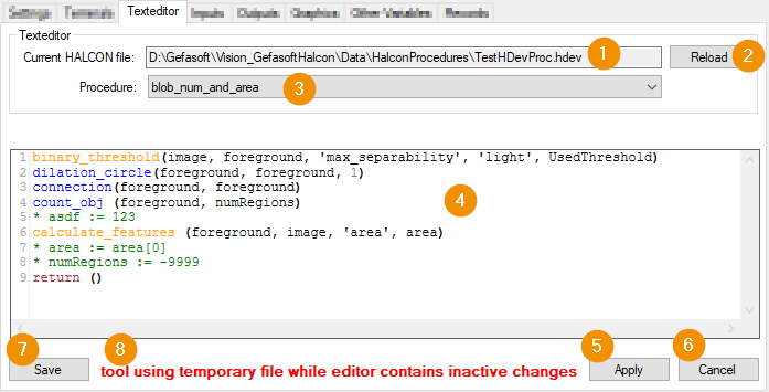
Current HALCON file: Path of the program file loaded in the tool.
Reload: Triggers a reload of the program file and the procedures it contains. Reloading discards unsaved source code changes in the editor.
Procedure: Name of the procedure currently displayed in the editor.
Editor: Display and edit the source code. Changes to the code will only be activated by confirmation via Apply or Save.
Apply: Applies code changes to the tool: When the tool is executed, the edited code then takes effect. However, the original source code file remains unchanged; the tool loads the changes from a temporary file. When the tool editor is closed, the persistently stored original state is restored. Only syntactically correct programs can be applied.
Cancel: Cancels code changes and restores the previous code state. Restoration takes place in two stages: if the editor contains changes that were neither applied nor saved, these are first reset so that the editor displays the currently executed code. Only then is the persistently stored code restored, thus discarding any changes that were activated by Apply. After the reset, the displayed and actively executed code are always identical.
Save: Saves the changes made to the program file. Only syntactically error-free programs can be saved. All changes within the program are saved, including those to procedures that are not displayed.
State: describes the displayed code state:
editor contains inactive changes indicates that the displayed code contains changes that are not actively effective during tool execution.
tool using temporary file indicates that code is active during tool execution that was last applied using Apply. However, the changes have not yet been saved and are lost when the tool editor is closed.
Inputs/Outputs Tab
The Inputs and Outputs tabs display all documented input and output parameters, such as images, regions, and control variables. The display is divided by parameter type into sub-tabs such as “Images”, “Regions” and “Control variables”. The “Outputs” tab is identical to the “Inputs” tab. The individual sub-tabs are explained below on the basis of the inputs.
Images Tab
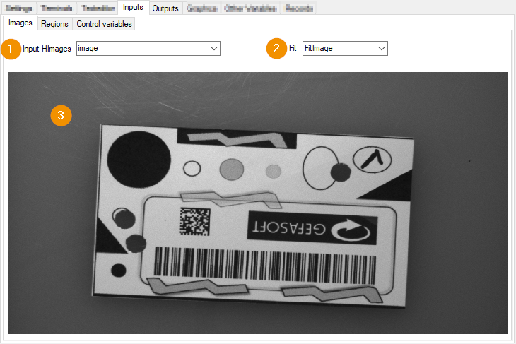
Input HImages: Selection of an image for display
Fit: Scaling of the image. FitImage fits the image into the window while maintaining the aspect ratio.
Display: Display of the image
Hint
The view is updated by running the tool
Regions tab
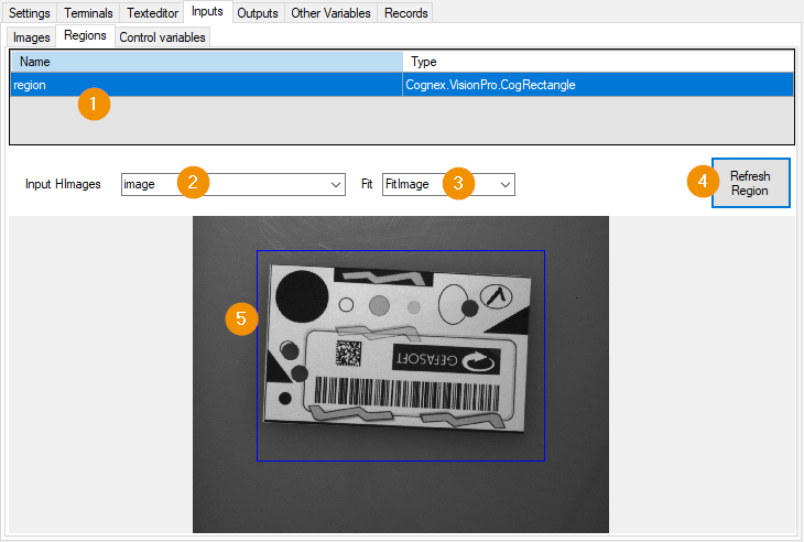
Regionlist: Shows the available parameters of type Region. The selected region is shown in the display.
Input HImages: Selection of an image as background of the display.
Fit: Defines the scaling mode of the image: FitImage fits the image into the window while maintaining the aspect ratio.
Refresh Region: Refreshes the display.
Display: Display of the selected region above the selected image.
Control Variables Tab
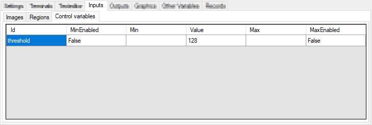
All Control parameters are displayed in a list. The columns show the following values:
Id: Name of the parameter
MinEnabled: Enable minimum
Min: documented minimum value
Value: Current value
Max: Maximum value
MaxEnabled: Enable maximum value