Set up cameras
The Vision plug-in supports the user in setting up new cameras with a number of functions.
After maintenance work, a wizard assists with alignment to a reference image. This reproduces the original camera images as best as possible to avoid changes to the sequences. Reference images should therefore always be stored in this wizard during initial commissioning.
Live image
Live image views continuously pull in and display new images. This allows the effects of configuration changes to be visually observed live.
Live images can be displayed directly in the Job-Display. To do this, the subdisplays must be assigned to the image source to be displayed in each case in the Live image settings. The live mode and the associated settings are activated via the Job-Display-Toolbar.
For each image source, a live-display can also be opened via the image-source-lists.
Continuous mode
In Continuous mode, the job and its currently selected ToolGroup item are continuously executed. The required images are always pulled in. During setup, it is thus possible to observe approximately live how changes to the image source settings affect the job result. The mode is started and stopped in the Job-Display-Toolbar.
Display functions
In the job display, special overlays help with camera setup. They are enabled/disabled in the Job-Display-Toolbar.

1. crosshairs
The crosshair supports the image direction by visualizing image center and axes by a cyanes overlay.
2. exposure warning
The Exposure warning supports the setting of aperture and exposure time: overexposed pixels in the sense of pixels with maximum gray value (for example 255 in 8-bit images) are colored red. Under-exposed pixels with minimum gray value (usually 0) are displayed in blue.
3. status bar
The status bar shows information about the image: the coordinates of the cursor position are displayed, measured in a selectable coordinate space. Next to it, the current zoom scale of the image is given. In the last column, the gray value of the image under the cursor position is displayed.
Angle and length measurement
In the job-displays, lengths between two points or angles between two straight lines can be measured interactively with the mouse cursor.

The functions are controlled by the function-panel of the shell.
Graphic Drag&Drop
Custom graphics can be added to the job-displays. For example, edges can be visually extended or geometric intersections can be targeted to optimize camera orientation. The feature can also support fault diagnosis by visually comparing features between images:
Inserted graphics are aligned to the pixel grid of the image and persist beyond acquisition of new images.
To insert graphics, the Drop-Graphics dialog is opened via the main-menu.
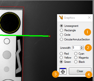
Before inserting a graphic, the desired shape (1) and its display options such as color and line width (2) are set. By drag and drop the new graphic is dragged from the crosshair symbol (3) into an image display.
The Clear button (4) deletes all custom graphics.
Reference image alignment
The “Align Imagesource tool” helps to reproduce original image source settings as good as possible, for example if a camera is replaced or if its position has changed. For this purpose, the tool places a current camera image next to a reference image in the mainview and measures differences within a definable search region. The user interactively minimizes the differences by adjusting the camera setting until satisfied with the result. For visual comparison in case of small image and position differences, it is also possible to switch to a overlayview. There, the reference image and the camera image are displayed alternately in one image view. Smaller image differences can thus be perceived as tremors.
Open the tool in the editor of a image-source-list.
Saving and loading reference images
To use the tool, a reference image must be available that shows the target state of the camera. The tool allows the import of any image. It is recommended to save a reference image for each image source with the tool itself after completing the initial commissioning. The image can show scenes from productive operation, but can also contain special reference objects. The latter is recommended if components cannot be placed reproducibly in front of the camera in a fixed image.
Hiterlegen von Referenzbilder im Tool erfolgt über die Toolleiste. First, a single current camera image is acquired via the Camera Image View> and checked. If the image is correct, it must be transferred to the *reference-image-view. There a relevant search region and overlay graphics can be defined. These are saved together with the image when saving via the Toolbar,
The tool stores reference images in the project directory inside the folder ./Data/ReferencImages/. The created files contain name and ID of the image-source for unique assignment. Existing reference images with the same name will be overwritten after confirmation.
To load reference images, the toolbar above the reference-image-view provides two options after clicking the open reference image button:
Open: If possible, automatically opens the reference image of the source that was last saved via the tool’s mechanism. Stored search regions and graphics are also loaded.
Import: Loads an image from a user-defined file. For example, stored input images from production can be loaded. In that case usually a warning is displayed, which states that loading associated search regions and graphics was not possible.
Main view

The Camera Image View (1) visualizes the actual state of the image source. The reference image view (2) shows a loaded image that reflects the target state. The toolbar (3) is used to control the image views or to switch to the Overlay view. Below each of the two image views there is a setting-region for defining a search region for source (4) and reference (5) images. The measurement area (6) contrasts measurement values from the respective search regions. Below this, information on the General Tool Status (7) is occasionally displayed.
Toolbar
The toolbar above each of the two views contains specific tools for controlling the displayed image in the view below:
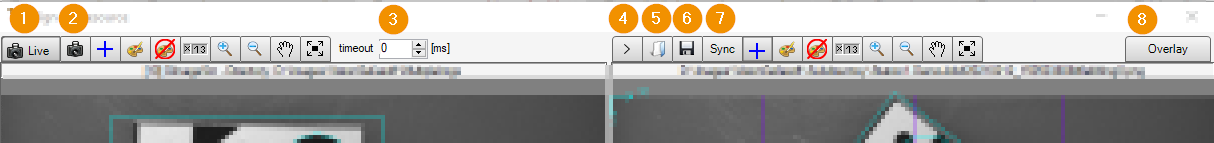
Toggle live mode: Enables/disables live mode in Camera Image View with continuous feed of camera images.
Get one image: Pulls in and displays a single camera image.
timeout: Waiting time for image acquisition in live mode. If the image acquisition takes longer, the live mode is terminated.
Clone image to reference display: Transfers the current camera image to the reference image view.
Open reference image: Loads a saved image into the reference image view. Two variants for loading are offered: Open and import. See section Saving and loading referece images
Save reference image: Saves the displayed reference image in the default path.
Synchronize both displays: Synchronizes display settings such as zoom level and image position of both image views.
Overlay: Switches to Overlay view
In addition, the two views can each be controlled by a set of identical tools:
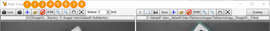
Change grid: Controls the display of a superimposed image grid: Pressing repeatedly sets the level of a superimposed grid and fades the grid in/out.
Edit graphics: Adds overlaid graphics to the view. The overlays are aligned with the pixel grid of the image. If the Apply to both displays option is enabled when the graphic is inserted, a duplicate of the graphic is inserted in the other view and the position of the overlays is synchronized. By overlaying visible features with graphics, their alignment can be visually compared in the two images.
Show/hide graphics: Enables/disables the display of inserted graphic overlays in the view.
Show/hide statusbar: Show/hide a status bar in the view.
Zoom in: Enlarges the displayed image by one level
Zoom out: Reduces the displayed image by one level.
Change cursor mode: Changes the mode of the mouse cursor between moving the image and editing the overlay graphics.
Fit image: Fits the image in the center of the view and fully visible.
Search areas
For camera and reference image, viewfinder regions can be defined in which the measured values are determined in the measured value area. The setting is made in each case below the image views:

After selecting a search area shape (1), the area can either be edited interactively in the image view (cf. Cursor mode in the Toolbar) or the corresponding definition parameters are entered numerically. The specification is always relative to the pixel grid of the image.
In the settings of the Reference image search region the option Synchronize both regions can be activated. Then the search region of the reference image is applied to both images.
Measured value range
Comparison values from the search regions of the reference image and camera image can be displayed in the measured value area.

Two value groups are supported:
Histogram: Within the respective search region, a gray value histogram is calculated in each image. The mean value of the gray values (Brightness) and the standard deviation (Deviation) are displayed as results.
Alignment: Within the search regions, the relative alignment of the images is compared using a pattern search. The search region in the reference image defines the search pattern. The location of the selected origin relative to the image are displayed under Origin. If the pattern is recovered within the camera image search region, the calculated position deviations are displayed in the Result column. The images are ideally aligned, if an offset and rotation of exactly 0 and a scale of 1 are displayed. If the option Show coordinate axes (6) is activated, the position pattern is displayed as a coordinate system in the image views: The reference pattern in cyan, the recovered camera image pattern in green.
Both evaluations are de-/activated via the respective Run button (3 and 4). The displayed images are then continuously evaluated. For interactive image source setup, the camera view should be switched to Live mode. The respective status lines (5 and 7) and the color of the value indicators inform about the evaluation status.
Overlay view
In the Toolbar you can switch between Mainview and Overlay View. The overlay view shows only one image view. The displayed image switches between the camera image and the loaded reference image in a configurable time interval.
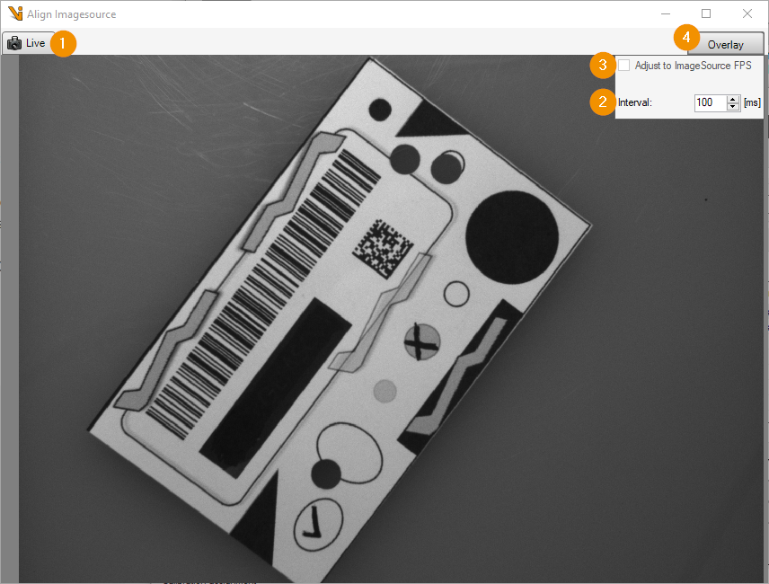
Live: Activates the live mode of the camera: the camera images are continuously redrawn.
Interval: Defines the time period after which the displayed image is changed.
Adjust to ImageSource FPS: If the camera is operated in live mode, the image interval can be defined by the framerate of the camera. With this setting, changes become visible as quickly as possible.
Overlay: Closes the Overlay view and switches back to mainview.
Small differences between the camera image and the reference image are perceived as jittering or flickering when the time interval of the image change is small. With an optimal camera setting, an almost motionless image is produced.