BushPositionDetectionTool
The BushPositionDetectionTool has been programmed to determine the position of identical, circular parts (e.g. disks, upright cylinders, bushings, etc.). It is used to classify these parts into grippable parts and non-grippable parts and to transmit the coordinates of the grippable parts (e.g. by a robot) to a higher-level controller. Only one coordinate is transmitted at a time, e.g. depending on the distance to the center of the image (configurable).
The general flow of the tool is as follows:
In a defined area, circular structures are searched for using CircleHough algorithm (CircleHoughTool). If structures with sufficiently high score are found, a fine search for circles is performed on these structures using the FindCircle algorithm (CogFindCircleTool). Subsequently, interference contours are searched for with a CogBlobTool between the circles found, in order to detect any fallen parts. For this purpose, a mask image is generated from the circles found so far. Found circles, which are too close to these dark areas (blobs), are declared as intangible. Also, parts whose determined centers are too close to each other (possibly overlapping) are marked separately (not tangible).
Detailed explanation based on an example:
In the example, flanged bushings are detected in a crate. The bushings are in several layers in a box with the collar downwards and could also have fallen over or be lying on top of each other due to transport. The individual layers are separated with light-colored cardboard.
result image

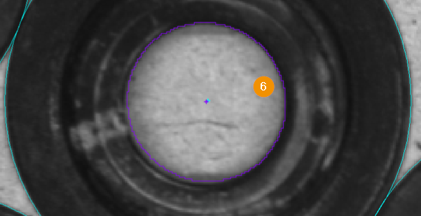
Blue (outer region): This region is searched for circles using CircleHough algorithm (CircleHoughTool).
Magenta (inner region): This region is used to search for fallen bushings or other interference contours (CogBlobTool).
Cyan (tangible sockets): Sockets that are outlined in cyan are accessible to the higher-level controller, i.e. their coordinates are passed on to the controller.
Red (overlapping sockets): Bushings which are outlined in red overlap, i.e. the centers of the circles found are too close. They are evaluated as not tangible
Orange (sockets too close to interference contour): Sockets outlined in orange are too close to an interfering contour, such as a socket that has fallen over. They are evaluated as not grippable
Purple (inner blob surface): The inner surface of the bushes is searched for and evaluated again (distance between the centre of the inner surface and the centre of the outer circle), in order to delimit any bushes that may be protruding from the underlying layer.
Hint
The inner region (magenta) must be set in such a way that there are no underlying, half-visible structures (bushings), e.g. by moving the intermediate layers.
Only the coordinates of exactly one socket are output.
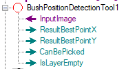
Outputs
Terminal |
State |
Description |
|---|---|---|
ResultBestPointX |
— |
Return of the determined X-coordinate |
ResultBestPointY |
— |
Return of the determined Y-coordinate |
CanBePicked |
0 |
No pickable socket available |
CanBePicked |
1 |
Pickable socket available |
IsLayerEmpty |
0 |
Layer available |
IsLayerEmpty |
1 |
No bushing (not even a fallen or overlapping one) available any more |
Note
IsLayerEmpty is used when the parts need to be picked from multiple layers and an intermediate layer can be removed.
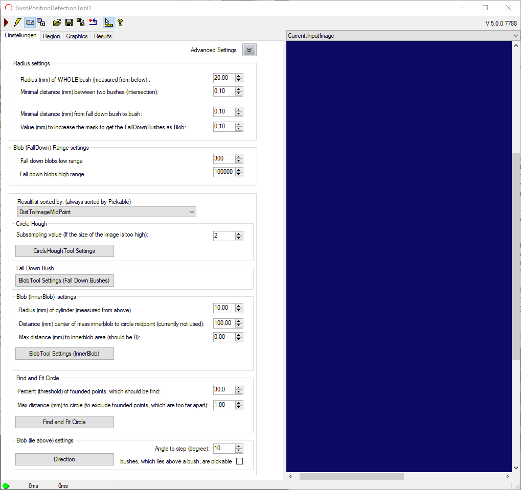
Settings:
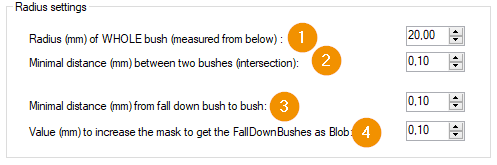
Radius (mm) of WHOLE bush: Radius of the circular object to be searched for in mm.
Minimal distance (mm) between two bushes: The centers of two objects must be at least twice the radius (from value above) including this value apart to avoid being declared overlapping (\(radius * 2 + minimum distance = actual minimum distance\)).
Minimum distance (mm) from fall down bush to bush: Minimum required distance between a bushing and an interference contour to mark the bushing as “graspable”.
Value (mm) to increase the mask to get the FallDownBushes as blob: Value by which the radius of found circles or bushes is increased for generating the mask image of the blob search for interfering contours.
Hint
The values refer to the SelectedSpaceName of the image. This is normally set to world coordinates (mm).
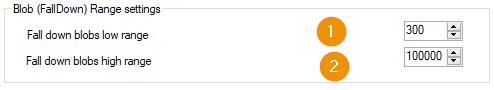
Fall down blobs low range: Minimum area above which dark areas between found sockets are evaluated as interference contours.
Fall down blobs high range: Minimum area up to which dark areas between found sockets are evaluated as interference contours.
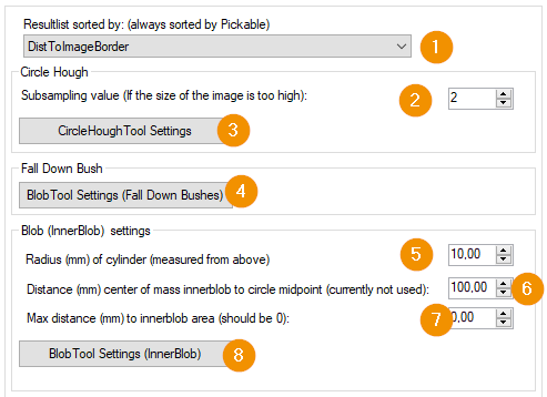
Resultlist sorted by: Order in which the coordinates of the tangible sockets are output. The following selection options are available here:
DistToImageBorder
DistToImageMidPoint
FirstByXThenByY
FirstByYThenByX
Subsampling value: The image is reduced by this factor (number of pixels) in order to reduce the computing time.
CircleHoughTool Settings: Opens the CircleHoughTool which is used within the BushPositionDetectionTool.
BlobTool Settings (Fall Down Bushes): Opens the CogBlobTool for searching interference contours or fallen down bushes.
Radius (mm) of cylinder: Nominal radius of the inner circle.
Distance (mm) center of mass innerblob to circle midpoint: Allowed maximum distance of the center of mass of the inner circle to the center of the found outer circle (to be seen at point 6 in the figure above -> purple and cyan colored point (value 100.0).
Max. distance (mm) to innerblob area: If the center of gravity of the blob lies outside of the actual blob area (e.g. for concave polygons), this value is the allowed distance of the center of gravity to the blob area (at 0: center of gravity must lie within the blob).
Blob Settings (Inner Blob): Opens the CogBlobTool for searching the inner circle.
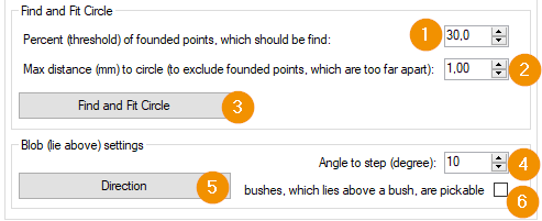
Percent (threshold) of founded points, which should be found: Percentage of calipers that must be found as a minimum during the fine search of the outer contour using CogFindCircleTool in order for an object to be evaluated as a bushing.
Max. distance (mm) to Circle: Allowed distance of the found points to the ideal circle, which is searched. Points with a greater distance to the ideal circle are discarded.
Find an Fit Circle: Opens the CogFindCircleTools to fine-tune the circular objects.
Angle to step (degree): If (6) is selected, collisions could occur at the edge of the search field after gripping a bushing if components are on top of each other. A CogBlobTool (5) is therefore used to examine the surroundings of the bushing step by step to determine a direction in which the bushing can be moved without collision. The direction vector is available in the Result under
DirectionXorDirectionY.Direction: Button opens the BlobTool for (4).
bushes, which lie above a bush, are pickable: Specifies whether bushes lying above each other should be marked as pickable.
Hint
The parameter Percent (threshold) of founded points, which should be found includes the number of calipers to be ignored, i.e. if many calipers are ignored, the parameter must also be corrected downwards.