Stations
In Viper.NET, stations represent a (bit-based) communication channel to an external system (PLC, robot, …). Often, stations also correspond to a physical processing or test station.
The handshake used depends on the station. A Standard BV station requires a different interface than, for example, the RunFromDir station for automatic reference image checking.
All stations are created in the configuration file stations.xml and initialized when Viper.NET is started. The stations tab shows the state of the handshake bits of the stations.
Digital standard handshake
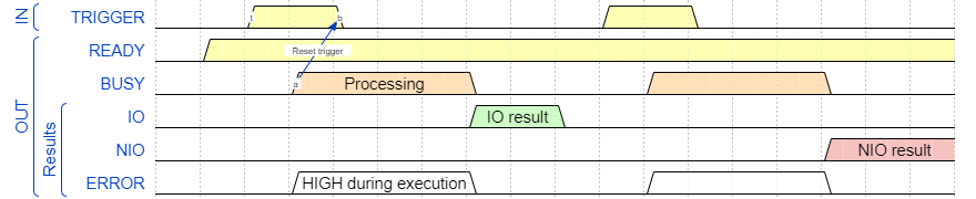
Digital handshakes in Viper.NET usually work on the principle of a three-way handshake with two signals TRIGGER and BUSY:
Timing diagram
First Viper.NET signals via READY->HIGH that the station is ready to receive triggers. The PLC can then start processing in Viper.NET via TRIGGER->HIGH.
Note
The TRIGGER may only be set by the PLC if the condition READY AND NOT BUSY is met. Otherwise the trigger is ignored by Viper.NET.
The station acknowledges the TRIGGER->HIGH with a BUSY->HIGH and starts processing. The PLC acknowledges the BUSY->HIGH signal with a TRIGGER->LOW.
Hint
The signal BUSY->LOW is only set by Viper.NET if TRIGGER->LOW is detected.
With the signal BUSY->LOW one of the three result bits is also set:
IO: Processing was completed with Good.
NIO: Processing was completed with Bad.
ERROR: An error occurred during processing, as a result of which no result could be determined.
This handshake forms the basis for most Viper.NET stations like the Vision Station, the RunFromDir Station or even the Reinspect Station.
Input data
In addition to the bits for the handshake, input and output data are defined for each station. The input data is read in at the trigger and used in processing. Since the time at which the data is read in cannot be determined exactly, and some data is also accessed during processing, the input data must not be changed during the process.
The data-areas for a station are normally divided into headers and payloads as follows:

Data areas Station
BITS: The bits of the handshake.
CMD: Can be used to trigger a specific command.
ERRCODE: Optional error code.
RESCODE: Optional result code.
CMD: Can be used to trigger a specific command. For BV stations, for example, this is used to switch between ToolGroup Items.
Note
In the documentation of individual stations, the significance of the individual fields for this station is explained in more detail.
Station configuration
All stations are created in the configuration file stations.xml. In addition to the configuration of the handshake bits and the input and output data, specific parameters are also specified here. The exact description of the configuration is given in the documentation of the respective station.
Note
After changes to configuration file stations.xml Viper.NET must be restarted.
In Viper.NET, depending on the plugin configuration, the following stations exist:
Viper.NET
Project specific plugins can provide additional stations.
Station Trigger Server
The stations can also be triggered by a TCP/IP or UDP telegram via the Station Trigger Server as an alternative to the TRIGGER bit. This has the advantage that the TRIGGER bit does not have to be polled. The cyclic data read in GInOut can then be done slower, or can be disabled completely. The handshake still corresponds to the Viper.NET standard. Only the edge change of the TRIGGER bit is replaced.
After changes to configuration file stations.xml Viper.NET must be restarted.
<triggerSvrs stationsExclusiveTriggerdBySvr="-1">
  <triggerSvr localIp="" port="4567" udp="False" maxTcpClients="100" timeoutWaitForTriggerBitHigh="-1" />
</triggerSvrs>
stationsExclusiveTriggerdBySvr : Comma-separated list of IDs of stations (-1 := all stations) to be started exclusively via the trigger server.
localIp : To bind the server port to a specific network adapter, a local IP address can be specified.
port : Local TCP/IP or UDP port.
udp: False|0 = TCP/IP connection, True|1* = UDP connection
maxTcpClients : Maximum number of TCP/IP connections (if udp=False).
timeoutWaitForTriggerBitHigh : Maximum time in [ms] that is waited for the digital trigger signal. The data is read cyclically.
< 0 : No waiting for the digital trigger signal.
0: The digital trigger signal must be set after updating the input data.
> 0 : The digital trigger signal must be set in [ms] after this time at the latest.
Request and response are pipe-separated NULL-terminated ASCII or UTF8 strings:
telegramId|stationId or dataId[0x00]telegramId|stationId or dataId|ACK[0x00]The telegramId can be freely assigned.
stationId : id of the station in the stations.xml.
dataId : id of the GInOut data to be read in (mode=UpdateData).
mode : Optional parameter, default value : “Slope”.
Slope : Positive and negative trigger slope
High : Positive trigger edge
Low : Negative trigger edge
Reset : Resets the station with the ID stationId. If stationId <= 0, all stations are reset.
UpdateData : The data with the specified ID dataId are read in from the hardware.
acknowledge:
Positive response : “ACK[0x00]”
Negative answer : “NAK:ErrorText”
99|1[0x00]99|1|ACK[0x00]99|1|NAK:Set starting outputs failed.[0x00]