Point Grey / FLIR
Before using a Point Grey / FLIR camera, the ‘SpinnakerSDK_FULL_2.2.0.48_x64.exe’ must be installed. On all LAN adapters with Point Grey / FLIR camera, the ‘Point Grey LightWeight Filter Driver’ must be activated.
General settings
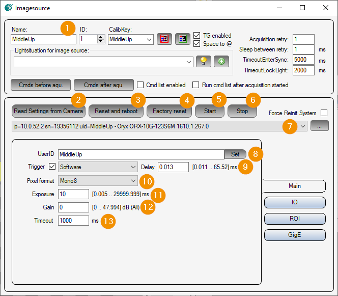
General Settings: Image Source Editor
Read Settings from Camera: Read all parameters from the camera and assign them to this image source or image acquisition parameter set.
Reset and reboot: Executes the command ‘DeviceReset’ on the camera. The camera is reset and rebooted.
Factory reset: Executes the command ‘FactoryReset’ on the camera. This resets the camera parameters to factory settings.
Start: Prepares the camera for image acquisition.
Stop: Exits the camera’s image acquisition mode.
Camera list: Selection list of all Spinnaker cameras. The list can be updated with the ‘… - button’ to refresh the list. If ‘Force Reinit System’ is activated, the Spinnaker systems (GigE and USB3) are reinitialized before searching for cameras.
UserID: Camera name that is stored in the camera by clicking the button ‘set’.
Trigger: If selected, the camera is in trigger mode. An image will only be captured when the trigger is released. The ‘Delay’ parameter can be used to delay the image acquisition. Depending on the camera type, one of the following trigger sources can be selected:
Software : Software trigger, triggered by Viper.NET during image acquisition.
Line0..3 : Hardware trigger at input 0 - 3.
Counter0/1End: Expiration of counter 0 or 1.
Pixel format: Pixel format in which the camera image is to be transmitted. Depending on the camera type, the following pixel formats can be set:
Mono8/10/12/14/16 : Gray scale image with 8/10/12/14/16 bits per pixel
BayerRG8/12 : Color image in red-green Bayer pattern with 8/12 bits per pixel.
RGB8 : Color image with red green blue pixels.
Exposure: Exposure time in [ms].
Gain: Analog gain factor (brightness).
Timeout: Maximum image recording time in [ms].
Inputs Outputs
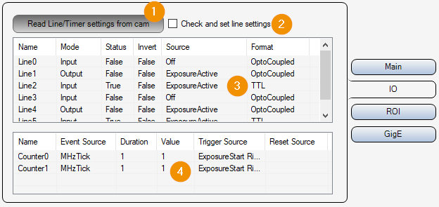
Read Line/Timer settings from cam: Read input/output and timer settings from camera.
Check and set line settings: If selected, the input/output parameters for this image acquisition parameter set are written to the camera before image capture.
Lines list: List of available inputs/outputs. Double-click on an element to open the parameter window for the corresponding input/output.
Counter list: List of available counters. Double-click on an element to open the parameter window for the corresponding counter.
ROI settings
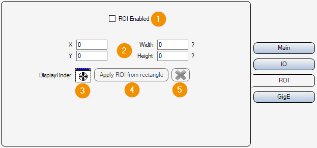
ROI Enabled: Enable or disable image cropping. If deactivated, the entire camera chip is read out and transmitted.
X/Y/Widht/Height: Selected image area. Position of the upper left corner, width and height.
DisplayFinder: With the display finder, a Cognex display (e.g. FormLive) can be selected via drag & drop, which is used for an interactive input of the image section.
Apply ROI from rectangle: Apply image section from rectangle of interactive input.
Cancel: Cancel interactive image selection (remove rectangle from display).
Gigabit Ethernet Settings
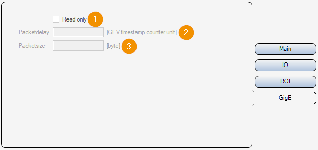
Read only:
On : Parameters 2-3 are only read out and displayed, but not changed.
Off : Parameters 2-3 can be set and changed.
Packet Delay: Waiting time in [ticks : converted time in [µs] is displayed next to the input field] between sending individual UDP data packets of the image data. This slows down the image data transmission and avoids possible data packet collisions or “overrun” of the LAN adapter or the PC.
Packetsize: Packet size in [byte] for the transmission of the UDP packets of the image data.