MicroEpsilon surfaceControl3D
The image source integrates surfaceControl3D sensors from MicroEpsilon. The image source can be operated either as a range image source or as a 2D grayscale image source. The two modes each require their own image acquisition. In Range mode, the source provides 2.5D data as a range image. In Intensity mode, the source provides an 8 grayscale image (image 2 by Master-Slave image sources) from each of the two cameras.
Installation and configuration
Warning
The Micro-Epsilon SDK uses the GigE driver of the Pleora eBUS SDK for sensor communication. The Cognex GigE-Vision driver uses the same SDK in a potentially different version. Before installing the device software, the Cognex GigE-Vision driver may have to be removed.
In vision projects with Surface-Control 3D Sensor no Cognex CogAcqFifo image source can be used and vice versa!
Warning
Pleora lists some network cards that may be incompatible or provide poor performance. See Pleora Support Center
The necessary Pleora eBUS SDK is automatically installed together with Micro-Epsilon_3D-View or Micro-Epsilon_3DInspect.
For the network card which is used to connect the SurfaceControl3D image source, the eBUS Universal Pro For Ethernet Driver must be activated. Pleora also recommends to adjust the following settings on the network card if possible (see Pleora Support Center):
jumbo packets / jumbo frames: “enable” [maximum]
Receive buffers / receive descriptors: “increase” [maximum]
interrupt moderation rate / interrupt throttling: “experiment” [maximum rate, no throttling]
turn off to save energy: switch off (in the configuration of the network adapter in the tab Energy management)
Image source settings
General
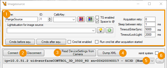
Generic settings, see image-sources editor
Connect / Disconnect: Triggers a manual connection attempt to the sensor or disconnects the connection. If the sensor is disconnected, an automatic connection attempt is performed each time the image is acquired.
Read device settings from camera: Reads the current sensor settings and applies them to the image source.
Dump XML: Writes all sensor settings to an XML file.
Device: Sensor hardware to which the image source refers. Connected devices can be selected from the drop-down list.
…: Updates the list of available devices. If reinit system is enabled, the MEGC system is completely reinitialized before searching for devices. For this purpose, all connected devices are disconnected!
Acquisition
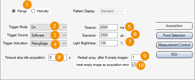
Range / Intensity: Switching the image source mode: Acquisition of 3D data or camera images.
Trigger Mode / -Source / -Activation: Selection of the signal source for starting an image acquisition. If the Trigger Mode is switched off, the device continuously acquires images. The image source then delivers the next incoming image after the image acquisition has started. Otherwise, the defined event triggers the acquisition. A software trigger is generated by the image source if necessary.
Timeout: Timeout for image acquisition (exclusive of possible TimeoutEnterSync wait times). After expiration the image acquisition will be aborted.
Exposure: Exposure time for image capture. In Range mode, multiple exposures are performed, and the time is multiplied accordingly.
Light-Brightness: Brightness of the built-in projector. It is recommended to set this to 100% as long as the exposure time can be shortened.
Patter Display: Pattern of the projector for illumination in Intensity mode.
Timeout stop idle acquisition: Timeout, der mit jedem Bildeinzug neu startet. Erfolgt innerhalb der angegebenen zeit kein weiterer Bildeinzug, so wird der Bildeinzug des Gerätes gestoppt. So kann beispielsweise im Intensity-Modus der Projektor abgeschaltet werden. -1 deaktiviert den Timeout, die Bildeinzugsschleife des Sensors läuft dann potentiell unbegrenzt. Der Wert muss stets größer als der Bildeinzugs-Timeout gewählt werden, sonst wird möglicherweise ein laufender Bildeinzug vorzeitig beendet.
Hint
The switching of parameter sets, extends the duration of the image acquisition considerably. If a toolgroup requires both range and intensity images or images of the same sensor with different settings, a sequential image acquisition can be activated for the job to avoid errors in the selection of suitable timeouts.
Repeated image acquisition with identical settings will start the sensor’s image acquisition loop only one single time. Occasionally, the sensor seems to enter an error state in which it delivers only empty range images. Remedy for such errors can be provided by the following parameters:
Restart acqu. after N empty images: Forces a restart of the sensor image acquisition after the specified number of empty images has been reached in immediate successive image acquisitions. Values <0 disable the function. When set to 0, a restart is forced with each image capture. A restart extends the duration of the image acquisition.
treat empty image as acquisition error: If active, an image acquisition error is triggered after receiving an empty image.
Hint
Simultaneously enabling treat empty image as acquisition error , setting Restart acqu. after N empty image =1 and Acquisition Retry>=1 causes image acquisition to be repeated immediately with a restart in case of an empty image. This way empty images can be avoided without extending the regular image acquisition time.
Point Selection
The tab parameters sumarizes GeniCam parameters, which determine the generation and selection of the measuring points in the range mode.
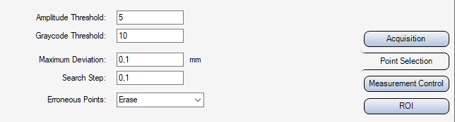
Amplitude Threshold: Minimum pattern contrast in the sine images
Graycode Threshold: Minimum contrast in the graycode images
Maximum Deviation: Maximum deviation of a calculated 3D point starting from the initial value (point cloud according to Graycode)
Search Step: Step size for the search in the Z-range
Erroneous points: Method for handling erroneous points, for example when MaximumDeviation is exceeded
Measurement Control
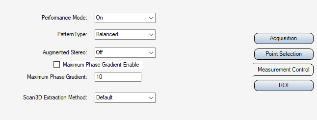
Performance Mode: Accelerates data processing at the expense of increased sensor temperature
PatternType: Projection pattern type
Augmented Stereo: As long asit is deactivated, the output includes only points that are perceived by both sensor-internal cameras. By activating the option, occlusions can be reduced. However, this may cause interfering points to become visible. If used, it is recommended to activate the Maximum Phase Gradient for outlier suppression.
Maximum Phase Gradient Enable: Enables/disables the Maximum Phase Gradient threshold.
Maximum Phase Gradient: Threshold value for sorting out outliers in the 3D point cloud.
Scan3D Extraction Method: Selects the point extraction method from the raw sensor data.
ROI
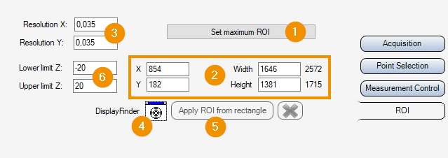
When operating the image source in range mode, the sensor only provides data in the range of the defined volume-of-interest. The volume is defined by a 2D region-of-interest as well as limits for the depth range (Sensor3D Z-coordinate). The sensor only provides points that lie within the measurement volume.
By clicking Set maximum ROI (1) the largest possible volume is set.
The offset of the 2D ROI (2) refers to the maximum possible image field. Width and height specify the dimensions of the output image. The physical size of an image pixel in x or y direction is indicated by the respective resolution (3). The ROI image section can be adjusted interactively in a display after an image with current ROI has been captured: By dragging the Display Finder crosshairs (4) onto a display, the ROI is shown there as an interactive rectangle, which can be adjusted. Subsequently clicking Apply ROI from rectangle (5) applies the parameters of the rectangle as the new ROI.
Upper and Lower limit Z (6) define threshold values for the measuring range. The thresholds refer to the Sensor3D coordinate space. Possible points outside are discarded by the sensor.
Plugin settings
In the Advanced settings of the Vision plugin some parameters can be adjusted, which apply globally toall devices:
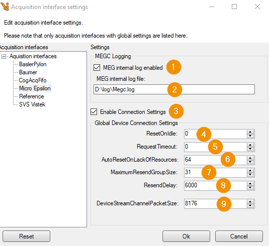
MEG internal log enaled: Enables the internal logging of the MicroEpsilon SDK. The log entries appear in the image source log data. The option always uses the maximum log level of the SDK.
MEG internal log file: Optionally a file path for storing the MicroEpsilon SDK logs can be specified. Only the MEGC internal logs arerecorded in it. The entries will still appear in the image source log. If the field is empty, no file is created.
Warning
The internal log file of the MicroEpsilon SDK does not follow the log4net logging configuration. The file size could possibly grow unlimitedly!
Enable Connection Settings: Activates the setting of connection parameters for communication with the sensor. The settings can be used in particular to improve the communication behavior in the event of network faults. The parameters are not persistently stored by the SDK or the sensor (with the exception of DeviceStreamChannelPacketSize). After a sensor restart, the device is therefore always operated with default parameters unless the option is activated.
Hint
If network errors occur, such as TOO_MANY_COSECUTIVE_RESENDS, these appear in the MEG internal log. As long as no errors occur the Connection Settings do not have to be adjusted. The meaning of error messages and parameters can be taken from the Pleora eBUS SDK if necessary. (cf. Pleora Knowledgebase)